Chapter 2 | Operation |
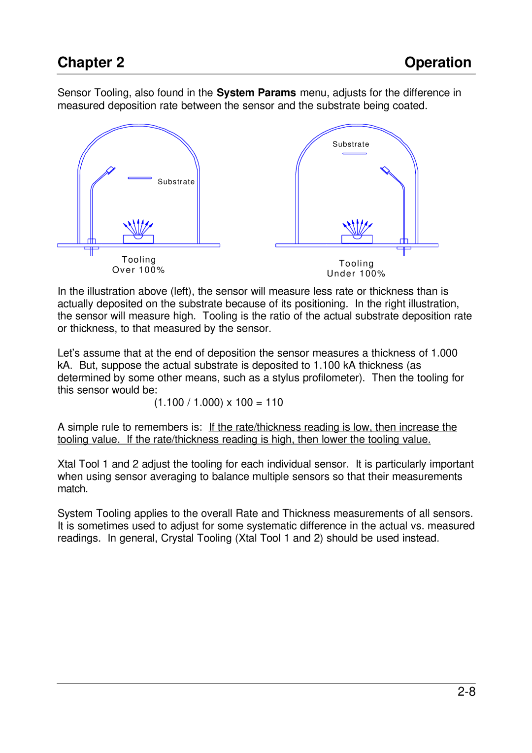
Sensor Tooling, also found in the System Params menu, adjusts for the difference in measured deposition rate between the sensor and the substrate being coated.
Substrate
S u b s t r a t e
T o o l i n g O v e r 1 0 0 %
Tooling U n d e r 1 0 0 %
In the illustration above (left), the sensor will measure less rate or thickness than is actually deposited on the substrate because of its positioning. In the right illustration, the sensor will measure high. Tooling is the ratio of the actual substrate deposition rate or thickness, to that measured by the sensor.
Let’s assume that at the end of deposition the sensor measures a thickness of 1.000 kA. But, suppose the actual substrate is deposited to 1.100 kA thickness (as determined by some other means, such as a stylus profilometer). Then the tooling for this sensor would be:
(1.100 / 1.000) x 100 = 110
A simple rule to remembers is: If the rate/thickness reading is low, then increase the tooling value. If the rate/thickness reading is high, then lower the tooling value.
Xtal Tool 1 and 2 adjust the tooling for each individual sensor. It is particularly important when using sensor averaging to balance multiple sensors so that their measurements match.
System Tooling applies to the overall Rate and Thickness measurements of all sensors. It is sometimes used to adjust for some systematic difference in the actual vs. measured readings. In general, Crystal Tooling (Xtal Tool 1 and 2) should be used instead.
