Appendix
C.I/O Connections
A 25 pin
Inputs can be activated either by connecting to a switch and shorting to Ground, or they can be driven by a TTL compatible signal.
WARNING: These are not isolated inputs! The voltage level applied must be limited to between 0 and +5 volts with respect to Ground.
WARNING: Output relays are rated for 30Vrms or 30VDC, at 2A maximum. Proper fusing, and adequate wiring insulation and separation, should be provided to assure these limits are not exceeded.
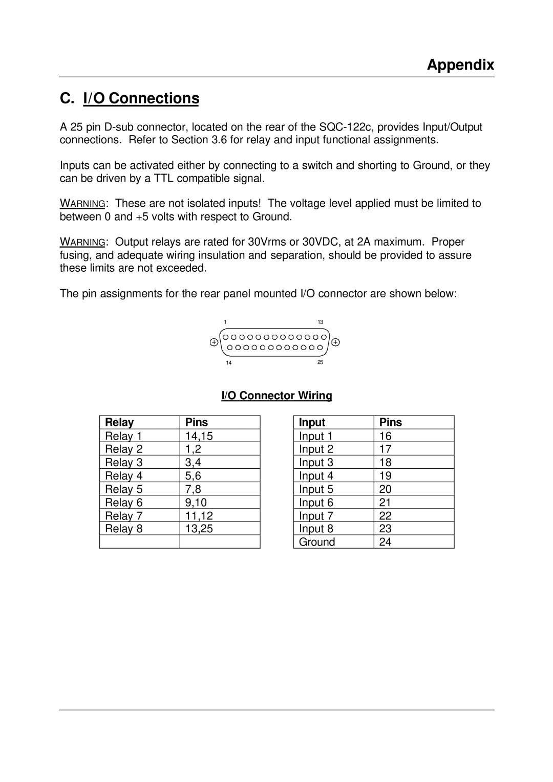
The pin assignments for the rear panel mounted I/O connector are shown below:
1 | 13 |
14 | 25 |
I/O Connector Wiring
Relay | Pins |
Relay 1 | 14,15 |
Relay 2 | 1,2 |
Relay 3 | 3,4 |
Relay 4 | 5,6 |
Relay 5 | 7,8 |
Relay 6 | 9,10 |
Relay 7 | 11,12 |
Relay 8 | 13,25 |
|
|
Input | Pins |
Input 1 | 16 |
Input 2 | 17 |
Input 3 | 18 |
Input 4 | 19 |
Input 5 | 20 |
Input 6 | 21 |
Input 7 | 22 |
Input 8 | 23 |
Ground | 24 |