5
Monitor/Control Reference Display for a Discrete, Relay, or
For a discrete, Relay, or
M N T R / C N T L (reference) I
S T A T E : O
N O F A U L T S
> o n o f f r e l e s
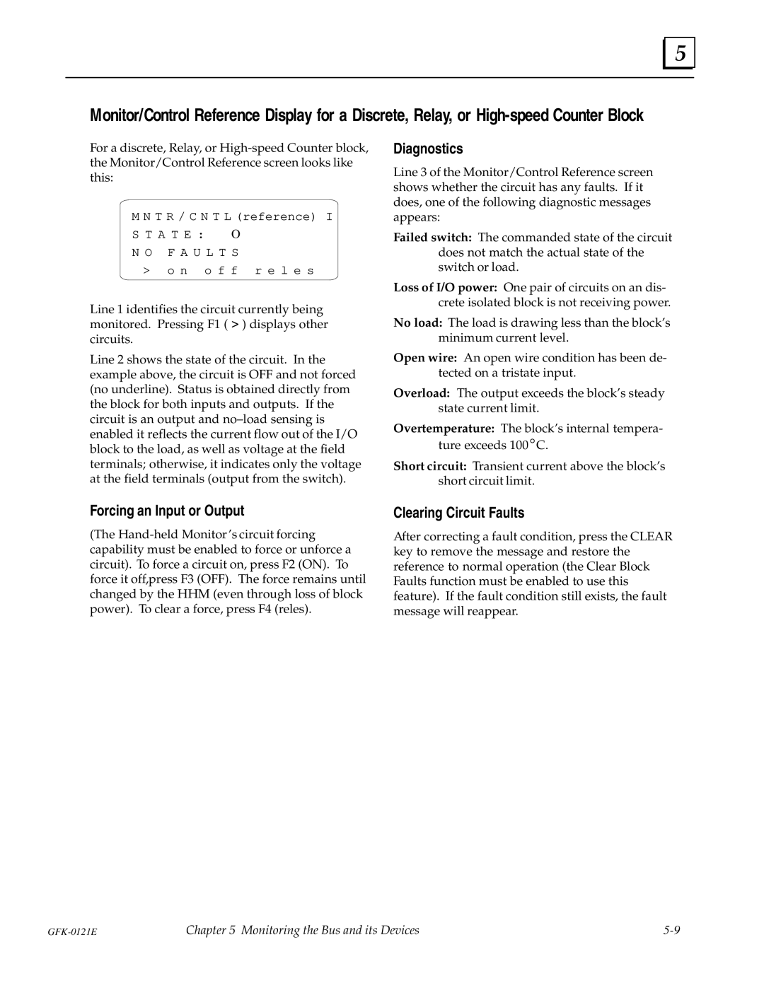
Line 1 identifies the circuit currently being monitored. Pressing F1 ( > ) displays other circuits.
Line 2 shows the state of the circuit. In the example above, the circuit is OFF and not forced (no underline). Status is obtained directly from the block for both inputs and outputs. If the circuit is an output and no±load sensing is enabled it reflects the current flow out of the I/O block to the load, as well as voltage at the field terminals; otherwise, it indicates only the voltage at the field terminals (output from the switch).
Diagnostics
Line 3 of the Monitor/Control Reference screen shows whether the circuit has any faults. If it does, one of the following diagnostic messages appears:
Failed switch: The commanded state of the circuit does not match the actual state of the switch or load.
Loss of I/O power: One pair of circuits on an dis- crete isolated block is not receiving power.
No load: The load is drawing less than the block's minimum current level.
Open wire: An open wire condition has been de- tected on a tristate input.
Overload: The output exceeds the block's steady state current limit.
Overtemperature: The block's internal tempera- ture exceeds 100_C.
Short circuit: Transient current above the block's short circuit limit.
Forcing an Input or Output
(The
Clearing Circuit Faults
After correcting a fault condition, press the CLEAR key to remove the message and restore the reference to normal operation (the Clear Block Faults function must be enabled to use this feature). If the fault condition still exists, the fault message will reappear.
Chapter 5 Monitoring the Bus and its Devices |
