5 |
Monitoring a Genius Block
Select F2 (Monitor Block) from the Analyze menu to:
HDisplay the I/O type of all circuits on the active block.
HDisplay (not change) forces on the active block.
HDisplay the bus presently selected by the BSM Controller.
Making the Block Active
If the block is not presently selected as the ªactiveº block, follow the steps below.
1.From the Analyze menu, select F3 (Block/Bus Status).
2.Press F1 (Next) or F2 (Previous), to reach the device's description screen.
3.When the block's screen appears, press F3 (Ac- tive) to make it the active device. (On a dual bus, the HHM must be on the same bus as the active block. If it is not, either move the HHM or force the bus selection)
4.Press D MENU to return to the Analyze menu.
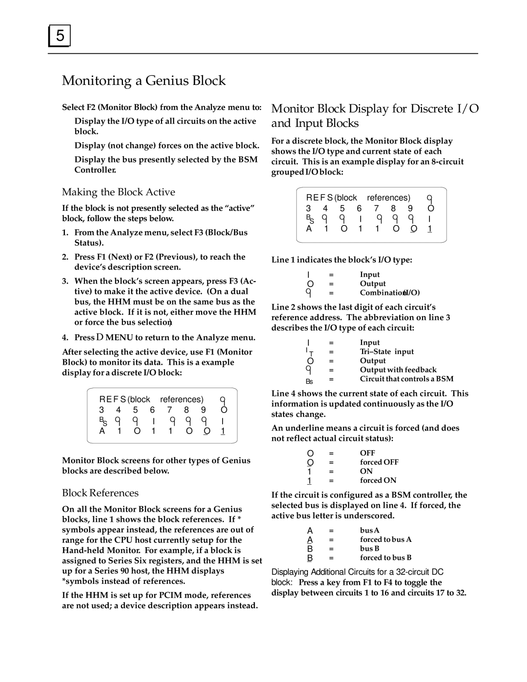
After selecting the active device, use F1 (Monitor Block) to monitor its data. This is a example display for a discrete I/O block:
Monitor Block Display for Discrete I/O and Input Blocks
For a discrete block, the Monitor Block display shows the I/O type and current state of each circuit. This is an example display for an
R E F S (block references) OI
3 | 4 | 5 | 6 | 7 | 8 | 9 | O |
BS OI | OI | I | OI OI OI | I | |||
A | 1 | O | 1 | 1 | O | O | 1 |
|
|
|
|
|
|
|
|
Line 1 indicates the block's I/O type:
I | = | Input |
O | = | Output |
O | = | Combination(I/O) |
I |
|
|
Line 2 shows the last digit of each circuit's reference address. The abbreviation on line 3 describes the I/O type of each circuit:
I | = | Input | |
IT | = | Tri±State input | |
O | = | Output | |
O | = | Output with feedback | |
I | = | Circuit that controls a BSM | |
Bs | |||
|
|
R E F S (block references) OI
3 | 4 | 5 | 6 | 7 | 8 | 9 | O |
BS OI | OI | I | OI OI OI | I | |||
A | 1 | O | 1 | 1 | O | O | 1 |
|
|
|
|
|
|
|
|
Monitor Block screens for other types of Genius blocks are described below.
Block References
On all the Monitor Block screens for a Genius blocks, line 1 shows the block references. If * symbols appear instead, the references are out of range for the CPU host currently setup for the
If the HHM is set up for PCIM mode, references are not used; a device description appears instead.
Line 4 shows the current state of each circuit. This information is updated continuously as the I/O states change.
An underline means a circuit is forced (and does not reflect actual circuit status):
O | = | OFF |
O | = | forced OFF |
1 | = | ON |
1 | = | forced ON |
If the circuit is configured as a BSM controller, the selected bus is displayed on line 4. If forced, the active bus letter is underscored.
A | = | busA |
A | = | forced to bus A |
B | = | bus B |
B | = | forced to bus B |
Displaying Additional Circuits for a