5
Monitoring/Controlling Remote Drop Data
The HHM can display diagnostics and currentI/O states, and force and unforce individual I/O points on I/O modules in a remote drop.
When the active device is a Remote I/O Scanner, the HHM's Monitor Block and Monitor/Control Reference functions display the same set of screens. This is unlike HHM operation for Genius blocks, where the screens for Monitor Block and Monitor/Control Reference are different.
For the Remote I/O Scanner, the monitoring screens provide the following information:
1.The states of the discrete inputs in the remote drop, in ascending order.
2.The values of the analog inputs in the remote drop, in ascending order.
3.The states of the discrete outputs for the re- mote drop, in ascending order.
4.The values of the analog outputs for the re- mote drop, in ascending order.
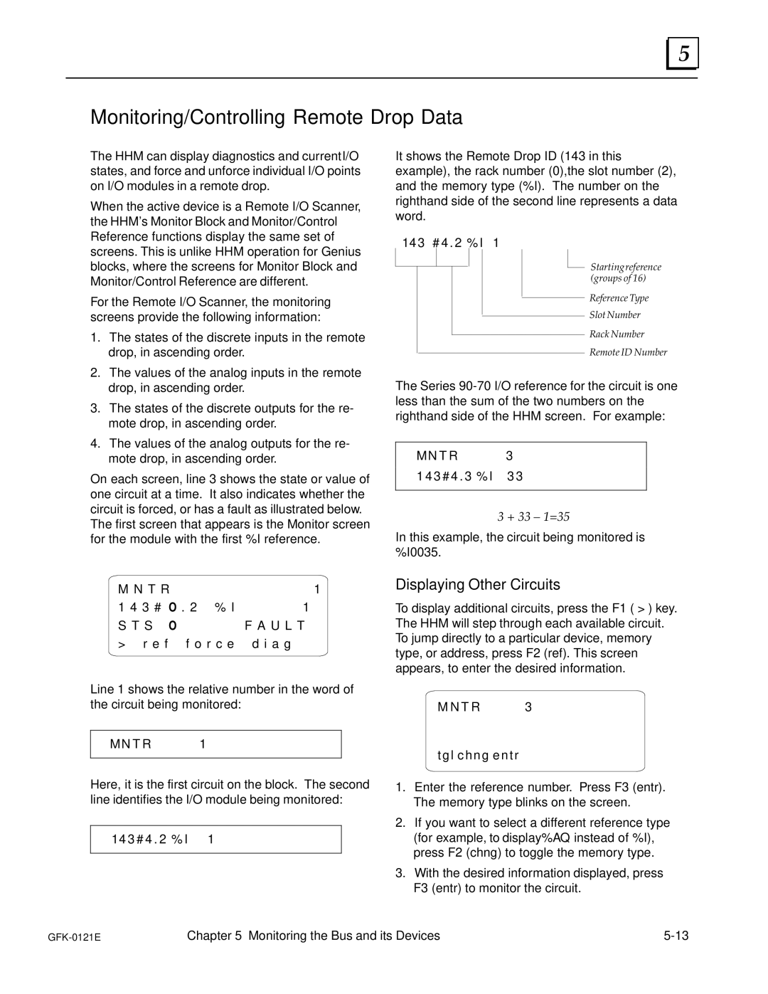
On each screen, line 3 shows the state or value of one circuit at a time. It also indicates whether the circuit is forced, or has a fault as illustrated below. The first screen that appears is the Monitor screen for the module with the first %I reference.
M N | T | R | 1 | |
1 | 4 | 3 | # O . 2 % I | 1 |
S T S | O | F A U L T | ||
> |
| r e f f o r c e d i a g | ||
|
|
|
|
|
Line 1 shows the relative number in the word of the circuit being monitored:
M N T R | 1 |
|
|
Here, it is the first circuit on the block. The second line identifies the I/O module being monitored:
1 4 3 # 4 . 2 % I | 1 |
|
|
It shows the Remote Drop ID (143 in this example), the rack number (0),the slot number (2), and the memory type (%I). The number on the righthand side of the second line represents a data word.
1 4 3 # 4 . 2 % I | 1 |
Starting reference (groups of 16)
Reference Type
Slot Number
Rack Number
Remote ID Number
The Series
M N T | R | 3 | |
1 4 3 # 4 . 3 % I | 3 3 | ||
|
|
| |
3 + 33 ± 1=35
In this example, the circuit being monitored is %I0035.
Displaying Other Circuits
To display additional circuits, press the F1 ( > ) key. The HHM will step through each available circuit. To jump directly to a particular device, memory type, or address, press F2 (ref). This screen appears, to enter the desired information.
M N T R | 3 |
t g l c h n g e n t r |
|
1.Enter the reference number. Press F3 (entr). The memory type blinks on the screen.
2.If you want to select a different reference type (for example, to display%AQ instead of %I), press F2 (chng) to toggle the memory type.
3.With the desired information displayed, press F3 (entr) to monitor the circuit.
Chapter 5 Monitoring the Bus and its Devices |
