4.Electrical connection to process machine:
•Injection Molding: Connect the cycle/run slave cable (thin
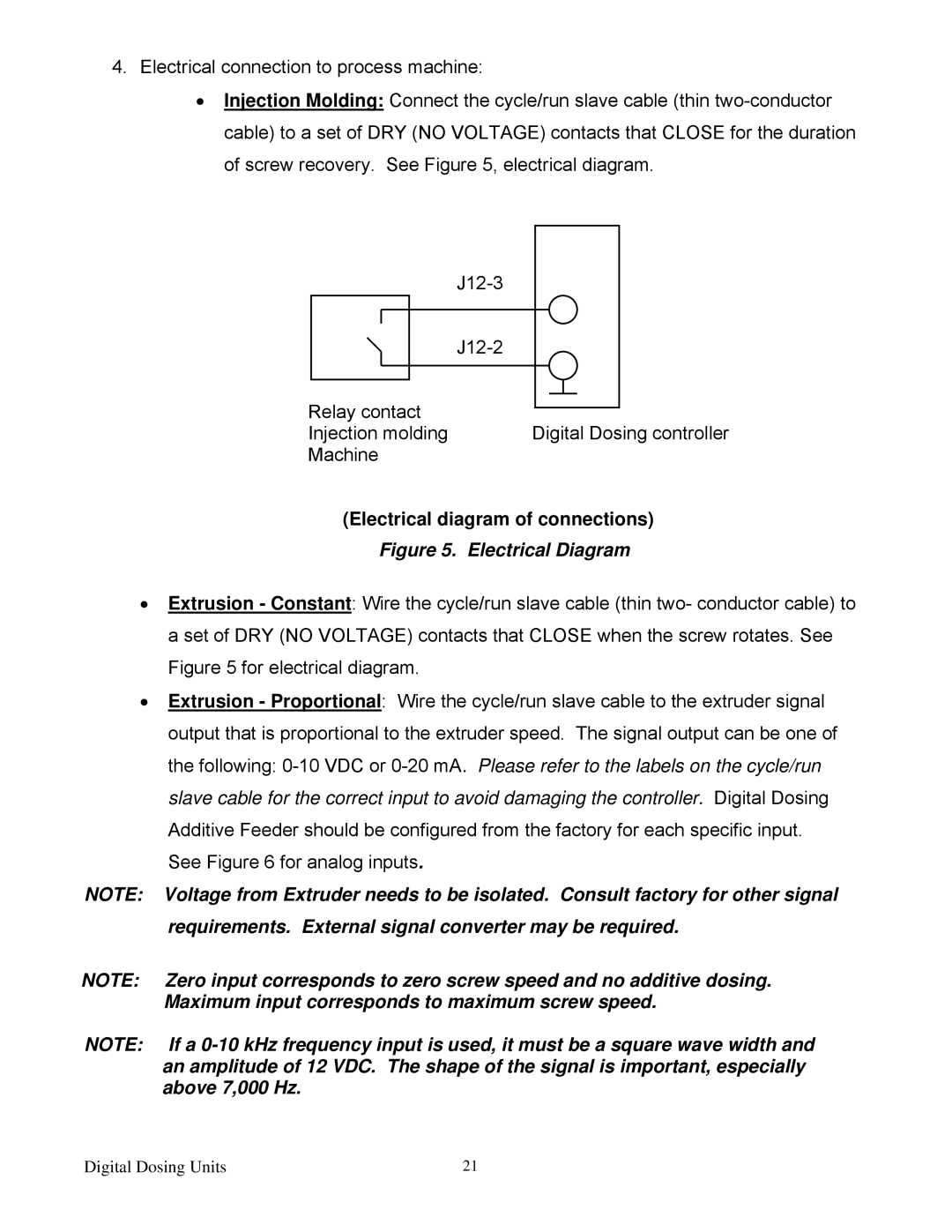
Relay contact
Injection molding Digital Dosing controller
Machine
(Electrical diagram of connections)
Figure 5. Electrical Diagram
•Extrusion - Constant: Wire the cycle/run slave cable (thin two- conductor cable) to a set of DRY (NO VOLTAGE) contacts that CLOSE when the screw rotates. See Figure 5 for electrical diagram.
•Extrusion - Proportional: Wire the cycle/run slave cable to the extruder signal output that is proportional to the extruder speed. The signal output can be one of the following:
NOTE: Voltage from Extruder needs to be isolated. Consult factory for other signal requirements. External signal converter may be required.
NOTE: Zero input corresponds to zero screw speed and no additive dosing. Maximum input corresponds to maximum screw speed.
NOTE: If a
Digital Dosing Units | 21 |