Virtual Tape Library
Page
Revision History
Iv VTL User Guide May
Contents
Understanding VTL Zoning
Using the VTL console
VTL operations
96267 G Contents
Viii VTL User Guide May
96267 G Contents
Snmp traps 243 Ilom command reference 275
Required ports 227 Troubleshooting 229
About this book
Next task
Taking advantage of this book’s hypertext features
Abcd
Understanding the conventions used in this book
Xiv VTL User Guide May
Introduction VTL appliances and enterprise data‐protection
Features
Features
Advantages of VTL tape virtualization
Shorter runtimes and reduced dependency on backup windows
Improved reliability
Shorter run times for non‐sequential backup jobs
Better utilization of tape subsystems
Larger, more flexible libraries
Improved utilization of backup media
Compatibility with Acsls management software
Advantages of VTL tape virtualization
Ndmp migration
Key VTL features and options
Server node failover
VTL high‐availability option
Management path failover
Failover during replication
Storage path failover
Mirroring and failover
Virtual tape replication
Automated Tape Caching
Replication
Auto Replication
VTL Secure Tape encryption option
Password protection
Key management
Zoning for standard‐availability systems
Understanding VTL Zoning
Wwpn zoning soft zoning
Zoning for high‐availability systems
WWPN2
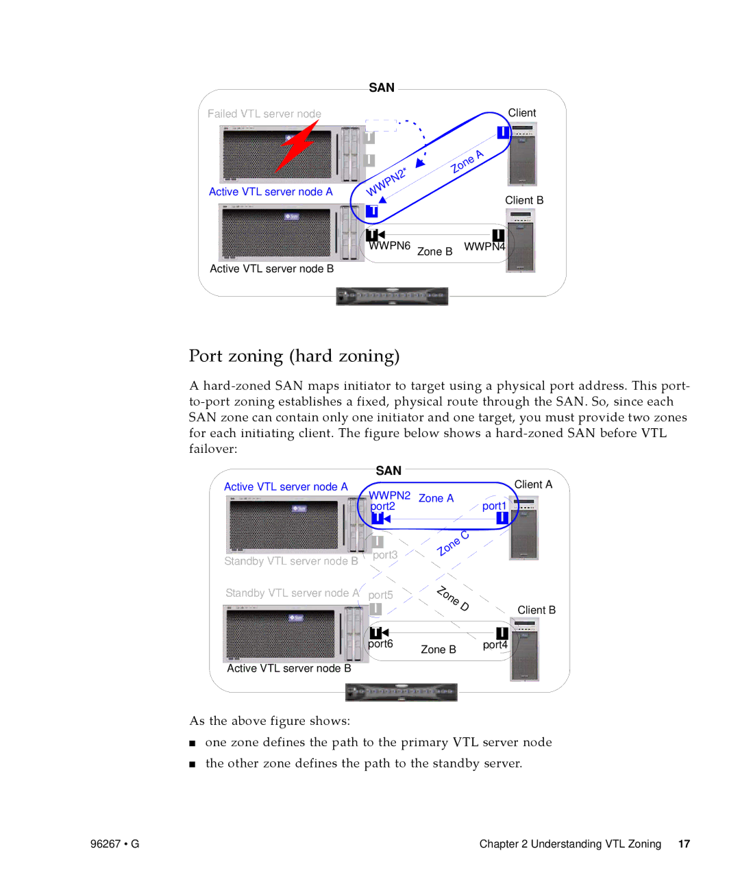
Port zoning hard zoning
ABC DE
Using the VTL console
Discovering VTL server nodes
Running the VTL console application
Populating the console
Launching the VTL console
Adding a server node to the console tree
Deleting a server node from the console tree
Understanding the VTL console interface
Physical Resources C above
Virtual Tape Library System icons
Virtual Tape Library System
Structure of the Virtual Tape Library System
Reports
SAN Clients
Physical Resources
Managing network connectivity
VTL operations
Configuring local area network connections
You return to the Network Configuration property sheet
Reconnect to the VTL server node. Stop here
Setting the VTL server node host name
Press OK B above
Obtaining SAN interface configuration information
Administering SAN client connections
Managing virtual libraries
Managing direct‐attached physical tape storage
Configuring physical libraries and devices
Preparing physical libraries and devices for assignment
Managing virtual libraries
When the Prepare Device panel appears, press Finish
Assigning direct‐attached physical tape libraries/devices
Managing Acsls and Library Station tape pools
Setting virtual library system properties
Configuring and provisioning virtual libraries
Press OK E above Stop here
Creating virtual tape libraries
Next G
Managing virtual libraries
Indicate if you want to use tape duplication
Configuring Automated Tape Caching
Creating state‐ and event‐based migration policies
Creating simple schedule‐driven migration policies
Next task Creating a reclamation policy on
Creating a reclamation policy
Setting up the Auto Archive feature
Setting up the Auto Replication option
Barcode Starts value in the text field provided a below
Generating the virtual library
Press Next D above
Sun recommends capacity on demand for most users
Enabling Auto Replication on an existing library
Managing virtual libraries
Enabling the advanced tape creation method
Creating virtual tapes
Below Press Next B
Selecting physical disk resources for use as virtual tape
Setting Auto Archive parameters for virtual tape volumes
Next task Allocating disk space to virtual tapes on
Allocating disk space to virtual tapes
Setting replication parameters for virtual tape volumes
RemoteserverIP VTL User Guide May
Managing virtual libraries
Launching the virtual tape batch creation process
Connecting virtual libraries with storage clients
Press Next K above
Starting the Add Client Wizard
Adding Fibre Channel SAN clients
Managing virtual libraries
Press Next B above
Starting the Assign a Virtual Tape Library Wizard
Client B, and press Next C
Assigning virtual libraries to storage clients
Discovering SAN virtual libraries from the Acsls host
Controlling VTL virtual libraries with Acsls
Log in to the Acsls server as root
Quiesce Acsls with the kill command
Perform a configuration reboot
Creating Acsls host driver instances for virtual libraries
Unload the unattached driver mchanger
Change to the Acsss home directory, and start Acsls
Adding virtual libraries to the Acsls configuration
Start the config acs new utility
Load the driver
When you are prompted, confirm the changes by entering y yes
Log the configuration events
Backing up the VTL system configuration
Automatically backing up the VTL configuration
Manually saving the VTL configuration
Managing virtual libraries
Select the Auto Save Config tab C below
Restoring the configuration
Recovering the server configuration
Protecting VTL metadata
Mirroring the VTL database
Managing virtual libraries
Removing a mirror configuration
Administering user acounts and passwords
Managing administrators
Virtual tape drive compression
Changing administrator passwords
To enable or disable compression
Searching for virtual tapes by barcode
Managing tapes
Locating virtual tapes
Replicating tapes
Setting up tape replication for multiple tapes
Managing tapes
Next N
Managing tapes
Next
Setting up replication for individual tapes
Managing tapes
Next M
Managing tapes
Next T
Managing tapes
Manually synchronizing replicas manual replication
Stopping a replication that is already under way
Suspending and resuming replication
Checking replication status from the primary VTL server
Checking replication status with a report
Checking replication status from the target VTL server
Changing replication properties
Promoting a replica resource
Deleting a replication configuration
Copying tapes
Copying a tape to a remote server
Nnn.nnn.nnn.nnn H
Moving tapes between virtual and physical libraries
Managing tapes
Importing a physical tape into a virtual library
Press Next G above
Express radio button K below, and press Next L
Managing tapes
Managing tapes
Managing tapes
Exporting virtual tape to physical tape
Importing cartridges in an IBM iSeries environment
Managing tapes
Select how you want the data exported
Indicate if you want to enable tape duplication
Rmvtapctg DEVlibrarydevicename CTGcartridgeidentifier
Renewing cache for a directly linked tape
Managing tape caching
Forcing migration to physical tape
Manually freeing cache space
Relinking physical tapes
Disabling a policy
Click OK Stop here
Managing tape caching
Creating a report
Creating and viewing reports
Press Next E above, then Finish Stop here
Creating and viewing reports
Creating and viewing reports
Viewing a report
Exporting data from a report
Encrypting and shredding data
Creating a key
Click OK E above Stop here
Changing a key name or password
Make the desired changes Click OK Stop here
Deleting a key
Exporting a key
Importing a key
Shredding a virtual tape
Encrypting and shredding data
Working with the Event Log
Sorting an event log
Viewing an event log
Filtering, exporting, purging, and printing an event log
Quickly printing an event log
Using the Attention Required tab
Clearing issues from the Attention Required list
Accessing the Attention Required tab
Configuring Snmp traps
Setting server properties
Managing VTL servers
You should see an Snmp trap for the event
Managing VTL servers VTL User Guide May
Installing the console on Solaris platforms
Installing the VTL console
Installing the console on Microsoft Windows platforms
Installing the console on Linux platforms
To launch the console, enter the following command
Launching the VTL console on a remote host
VTL User Guide May
Initiating failback
Failback
Make sure that you are logged in to the actual, active node
Run the vtl status command
Mgthostuser# ssh vtladmin@nnn.nnn.nnn.nnw
Make sure that you are logged in to the actual, failed node
Mgthostuser# ssh vtladmin@nnn.nnn.nnn.nnx
Run the vtl status command
Log in using the VTL management console
Mgthostuser# ssh vtladmin@nn.nnn.nnn.nnx
Run the vtl status command
VTLPlusvtladmin# sms
Resuming backups following a failover/failback
Page
Configuring email alerts
Next G
96267 G Configuring email alerts
Modifying email alerts properties
96267 G Configuring email alerts
Press OK to exit the Set Email Alerts Properties dialog
Applying patches
Updating VTL software
VTL User Guide May
Descriptionofpatch
VN.N Nnnn
Commands
Using the command line utility
Short Argument Long Argument Value/Description
Common arguments
Log in to the VTL Server
Login/logout to the VTL Server
Log out from the VTL Server
Virtual devices / Clients
Get virtual device list
Get Client virtual device list
Delete client
Add client
Assign virtual device
Get client properties
Unassign virtual device
Delete virtual device
Create virtual device
Get supported virtual libraries
Create virtual tape library
Get supported virtual drives
Description
Add virtual tape drive
Create standalone tape drive
Create virtual tape
Move virtual tape
Iscon movevirtualtape --server-name=server-name
Set tape duplication
Tape copy
Set tape properties
Description
Set tape caching
Automated tape caching
Description
Sync physical tapes
Migrate virtual tapes
Renew cache
Reclaim disk space
Add a license keycode
System configuration
Get VTL info
Remove a license keycode
Import tape
Import/Export
Export virtual tape
Get import/export job status
Description
Resume import/export jobs
Delete import/export jobs
Cancel import/export jobs
Suspend import/export jobs
Create a replica
Replication
Replication
Remove replication
Promote a replica
Suspend replication
Set replication properties
Resume replication
Get replication properties
Start replication
Get replication status
Stop replication
Physical devices
Inventory physical tape library
Move physical tape
Get physical tape list
Eject physical tape
Unassign physical resource from VTL
Assign physical resource to VTL
Get physical device information
Import disk
Rescan physical devices
Prepare physical device for VTL server
Server throughput report
Reports
Scsi channel throughput report
Device throughput report
Disk usage report
Physical resources configuration report
Specific physical resource allocation report
Physical resources allocation report
Replication status report
Fibre Channel adapter configuration report
Tape
Virtual library information report
Virtual tape information report
Create job report
Get Event Log
Event Log
Get X‐Ray
Technical support
Get attention required information
This commands displays the attention required messages
Required ports
VTL User Guide May
Case Connection fails before login
Problems during console operations
Case Connection fails while checking the VTL license
Case Connection fails during log
Case Low host system memory
Case Connection fails while expanding the VTL server node
Case High server activity
Problems affecting physical resources
Indications
Problems with virtual resources
Are displayed in the form /dev/st/index, /dev/nst/index
Case Applications cannot see the device
Case The operating system cannot detect the device
Case The backup application cannot see the device at all
Case Tape devices and/or media types are mismatched
Problems during import/export operations
Case The operating system cannot access the device
Case The operating system can access the device
Case Virtual tape barcodes duplicate physical tape barcodes
Case The export/import job is not complete
Case a physical tape library or device is not ready
Taking an X‐ray for technical support
Case Some other system error is causing the problem
Taking an X‐Ray
96267 G Appendix C Troubleshooting
VTL User Guide May
Snmp traps
Day schedule
96267 G Appendix D Snmp traps
Additional information
96267 G Appendix D Snmp traps
Guid %3
Continue
11170 Error
96267 G Appendix D Snmp traps
VTL User Guide May
11298 Error
11536 Informational
Failover configuration
11575 Error
11651 Error Medium Test failed for Scsi device %1 11652
3s was rolled back
%3 at about %4
2HBInterval %5AutoRecovery %6
Inc. or its representative to purchase a license
Failover not initiated
Storage
15053 Error
19051 Informational
22005 Error
25001 Error Failed To start -- %2 25002 Informational
Time
SrcTape %5 Throughput %6 MB/min
VTL User Guide May
40074 Error
40102 Error
40127 Informational
VTL User Guide May
Ilom command reference
Change the host serial port configuration
Delete this device from an Snmp private
VTL User Guide May