SyncServer S100
On the S100 Rear Panel
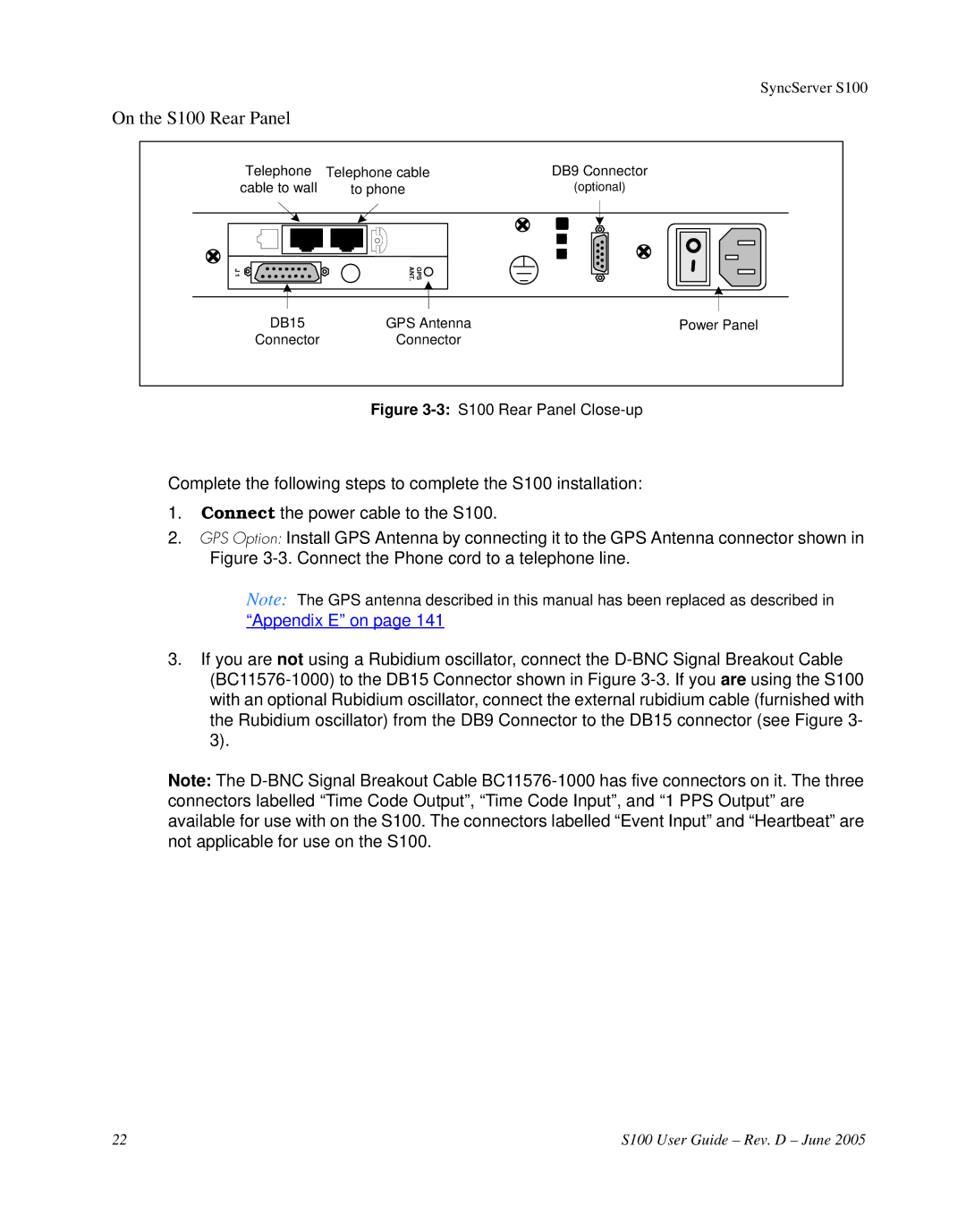
Telephone | Telephone cable | DB9 Connector |
cable to wall | to phone | (optional) |
J 1 | GPS ANT. |
|
DB15 | GPS Antenna | Power Panel |
Connector | Connector |
|
Figure 3-3: S100 Rear Panel Close-up
Complete the following steps to complete the S100 installation:
1.Connect the power cable to the S100.
2.GPS Option: Install GPS Antenna by connecting it to the GPS Antenna connector shown in Figure
Note: The GPS antenna described in this manual has been replaced as described in
“Appendix E” on page 141
3.If you are not using a Rubidium oscillator, connect the
Note: The
22 | S100 User Guide – Rev. D – June 2005 |