Total Organic Carbon Analyzer | Installation | |
|
|
|
All operator controls and serviceable components are mounted on the control panel, which is hinged and doubles as the door that provides access to those components not normally requiring maintenance.
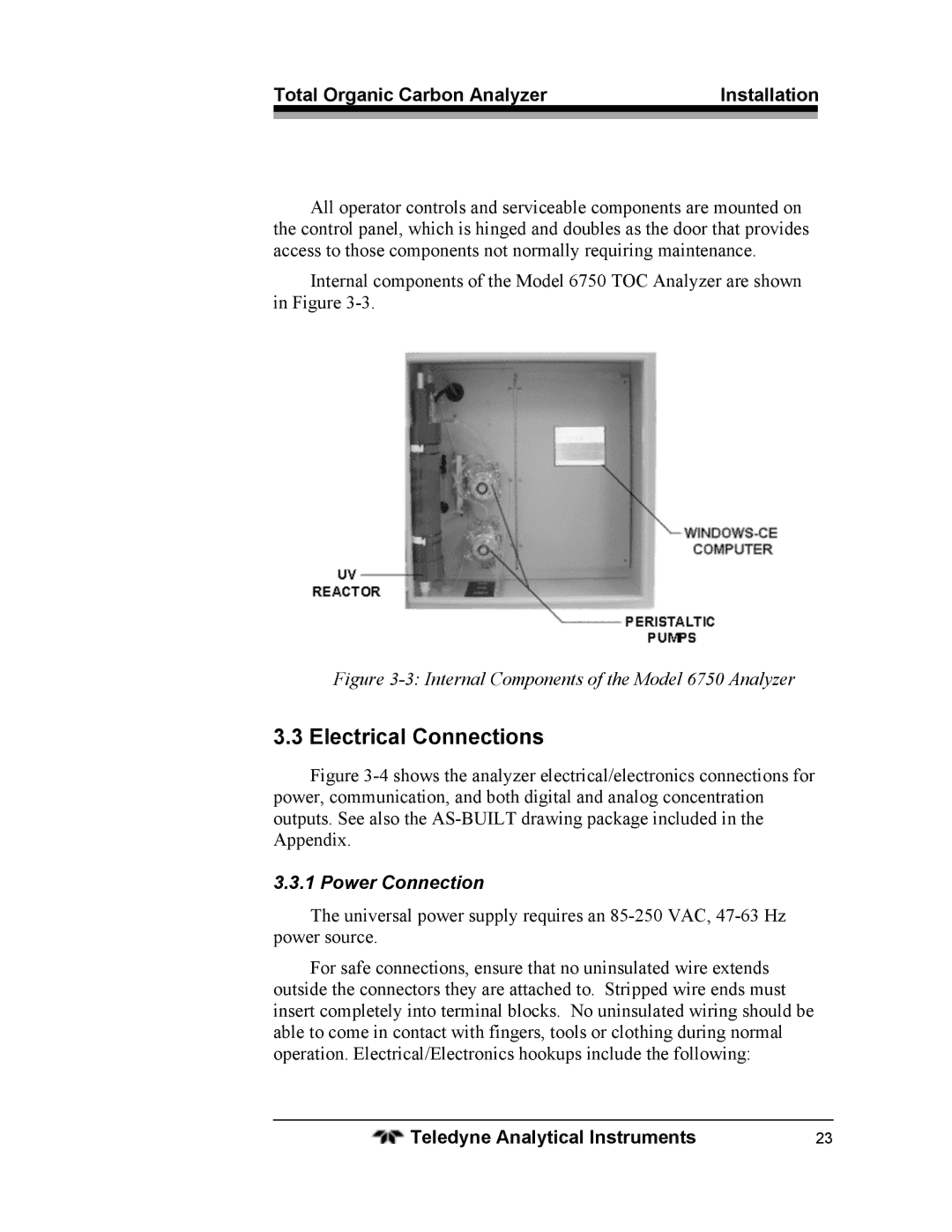
Internal components of the Model 6750 TOC Analyzer are shown in Figure
Figure 3-3: Internal Components of the Model 6750 Analyzer
3.3 Electrical Connections
Figure 3-4 shows the analyzer electrical/electronics connections for power, communication, and both digital and analog concentration outputs. See also the AS-BUILT drawing package included in the Appendix.
3.3.1 Power Connection
The universal power supply requires an
For safe connections, ensure that no uninsulated wire extends outside the connectors they are attached to. Stripped wire ends must insert completely into terminal blocks. No uninsulated wiring should be able to come in contact with fingers, tools or clothing during normal operation. Electrical/Electronics hookups include the following:
Teledyne Analytical Instruments | 23 |