Setup and Operation | Model 6750 |
|
|
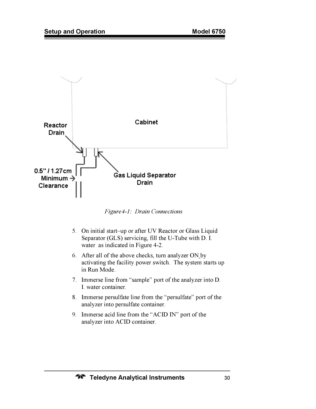
Figure4-1: Drain Connections
5.On initial
6.After all of the above checks, turn analyzer ON by activating the facility power switch. The system starts up in Run Mode.
7.Immerse line from “sample” port of the analyzer into D.
I. water container.
8.Immerse persulfate line from the “persulfate” port of the analyzer into persulfate container.
9.Immerse acid line from the “ACID IN” port of the analyzer into ACID container.
Teledyne Analytical Instruments | 30 |