UserÕs Manual
Manual Version 1.0 / April
What youÕve got here
Customer Service
Feedback
Test Lines
Blank Screen?
ZephyrExpress will dial a test line for you
Warranty
Updates
Power Supply
Trademarks
Repairs
Table of Contents
Isdn Reference
Troubleshooting
Schematics and Data Sheets Appendix
System Functions
Introduction
H i c t
Block Diagram
Menu Structure
Utility Menu
Quick Results
Tune into one of our test lines
Part
Quick Results
Gather information about your Isdn line
Isdn telephone numbers with area code
Isdn type, check one
MSN numbers, i f supplied Euro ETS300 only
Set up the hardware
Quick Results
HConfigure ZephyrExpress for your Isdn line
Quick Results
Call yourself testing your unit and the line
Configure the Codec
HOT TIP
Set up an audio input and output
Place the call to yourself
Quick Results
Tune into one of our test lines
Isdn TIP
What do I do if IÕm totally lost?
Fast Answers to Frequently-Asked Questions
He Basics
Knob either direction to change the LCD Contrast
How do I use the menus?
Scrollbar Highlighted
How do I enter numbers or names?
How do I use a menu that appears locked?
How do I lock a specific menu?
Right
H6 How do I create my own Setups and Master Setups?
HOT TIP
How do I manually enter a network setup?
How do I test that IÕve set things up properly?
Alternate test procedure
What do I do if I canÕt connect?
Audio setup How do I set ZephyrExpress for my microphones?
How do I use line-level sources?
How do I test my audio and compression setups?
How do I create a monitor mix?
Isdn Connection How do I place a call?
What do I do if they canÕt hear me?
HHOT TIP
How do I send a test tone?
How do I hang up?
Where do I find answers to other questions?
Circuit information · 1-4 coding methods ·
Quick Results
Zephyrexpress Hardware
About our hardware
Front Panel
Mixer Section
Send Mixer
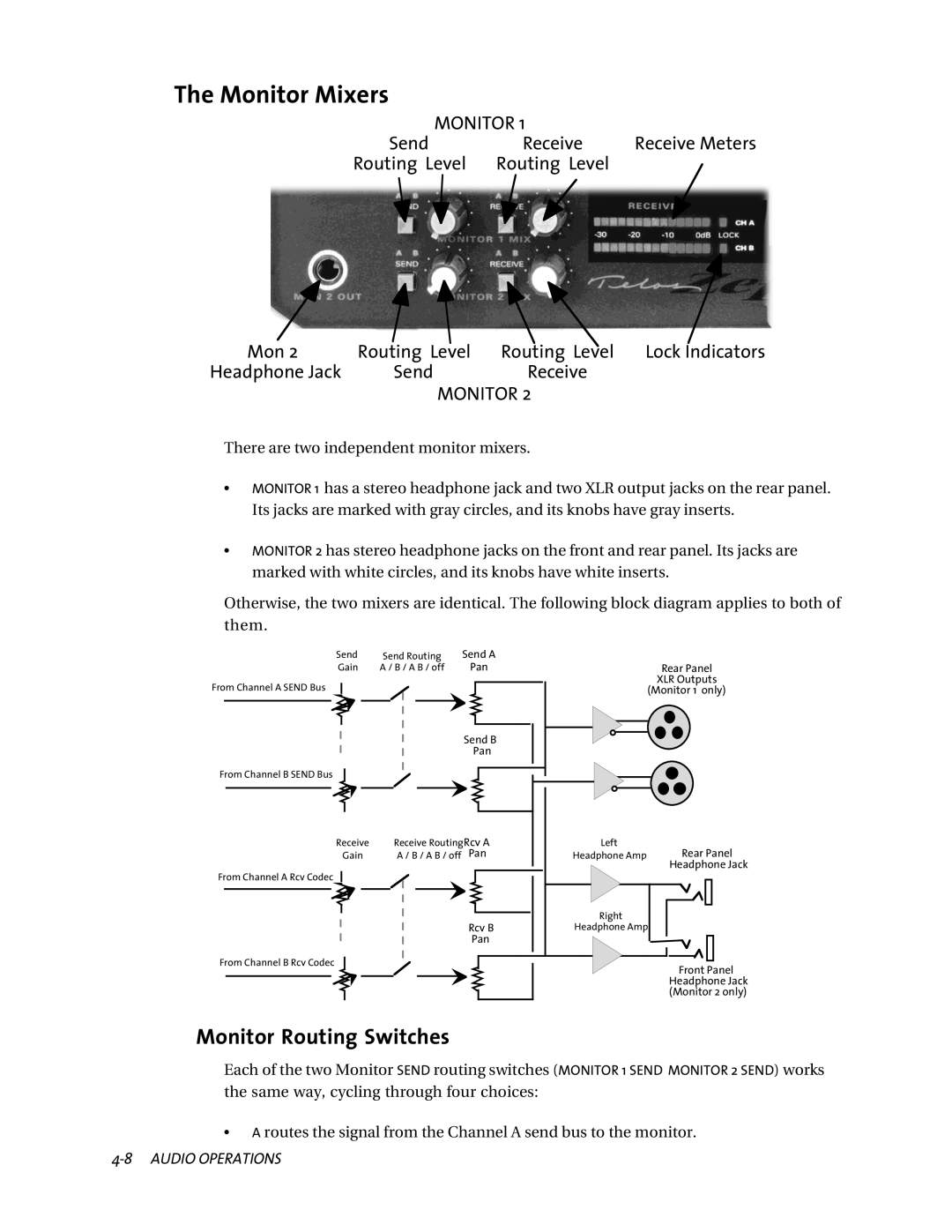
Monitor Mixers
Level Controls
Send and Receive Meters
Display section
Lock LEDs
LCD Display
Control section
Edit knob
Dial button
Drop button
Rear Panel
Data connection section
Mode switches
Isdn Connections
Interface Pinouts
Remote Control jacks
Line C Top pin
Inputs
RS-232 Pinouts
Parallel Port
Output 12 N/C Input 15 N/C
Audio i/o section
About the XLR Connectors
Outputs
ZephyrExpress
All XLR Pinouts
Microphone Inputs
Ground Audio +
Monitor 1 XLR outputs
Line Inputs
Conductor Input plug
Direct Isdn Receive outputs
Monitor 1, Monitor 2 Headphone outputs
Power connection
Power Supply Jack
Headphone Jacks
Power Supply XLR Output
Power Input
+5Vdc @ 5A +12Vdc @ 1.5A 12Vdc @ .5A System Ground
Zephyrexpress Hardware
Zephyrexpress Hardware
Audio Operations
Console at your fingertips
Mix flexibility
Send Mixer
Routing
Beware the Phantom
Mic Routing Switches
Compression, will make any perceptual coder less efficient
Routing, convert the mic inputs to line-level
Line Routing Switch
Gain
Bold Face Front Panel Hardware
Send Level Controls
Send Meters
Receive Meters
Monitor Routing Switches
Monitor Mixers
Send
About Monitor Panning
Adjusting individual monitor panning
Monitor 1 Send
Receive Meters
Lock lights
Receiving calls
Analog call signal routing
Analog G.711 phone calls
Talkback and cues can cut the cost of remote broadcasts
Placing calls
Hanging up
Mix-Minus
Dealing with Delay
Phones and Remotes
Remote Site
Audio Operations
Layer 3 Features
Compatibility
Overview
Introduction to Audio Coding
Basic Principles of Perceptual Coding
Coding
Layer 3 Features
Psychoacoustic Masking
Ancillary Data
Redundancy Reduction
Bit Reservoir Buffering
Bands
Layer 3 Joint Stereo
Layer 2 Joint Stereo
722
Layer 2 Mono-128
Cascading
Mixed Mpeg Layer 2 And Layer 3 Signal Chains
Audio Freq. Response/stereo
Audio Coding Comparison Chart
Algorithm Audio Freq. Response/mono
Layer 722
With one transmission path
Delay vs. Quality
Dual vs Stereo vs Joint Stereo in Layer
With two transmission paths
With one transmission path
Dual Site Operation
Layer 2 Mono64kpbs vs MONO128 Dual vs Jstereo
With two transmission paths
Sampling Rate
Between Telos Codecs
Compatibility
With Non-Telos Equipment
Coding
Coding
Codec menu Audio menu Isdn menu System menu Safe mode menu
Autodial Setups
Menu Overview
Menu System
Typical menu
Navigation Shortcuts
Getting Help
Weõre not Fortune Tellers
Menu Overview
Utility Menu
Applying a Setup
Using Setups
Creating or Changing a Setup
Master Setups
Applying a Master Setup
Creating or Changing a Master Setup
Auto-creating a new Master Setup
Updating an existing Master Setup
Manually creating a Master Setup
Deleting a Master Setup
Creating a new Autodial
Autodial Setups
Editing or deleting an Autodial
Menu Details
Codec menu
Isdn TIP
Audio menu
See , Audio 75 dB @ 100 Hz -10 dB @ 40 Hz
Isdn menu
Directory Number 7 digits
System menu
Seconds Minute Minutes Minutes Never
Safe mode menu
Menus
Background Basic Rate Interface BRI
Ordering Central Office Switches and Protocols
ZephyrExpress Isdn Compatibility
Isdn Basics
Background
Basic Rate Interface BRI
Isdn TIP
Spids
Get the SPIDs
Get the SPIDs
Directory Numbers DNs
Long-Distance Digital Connectivity
Switch carriers
Dealing with The Phone Company
Details, Details
CSD and CSV
NT1s
ZephyrExpress Isdn Compatibility
Protocols
Terminals and Terminal Types
Ordering Central Office Switches and Protocols1
National ISDN-1 USA and Canada
Zephyrexpress Settings for YOU to Enter
AT&T Point-to-Point Custom USA, Japan, Israel, some others
Zephyr Settings for YOU to Enter
AT&T Point-to-Multipoint Custom
Euro-ISDN Europe, Hong Kong, some others
Isdn
System Functions
Software Updates
Introduction
ZephyrExpress data ports
Serial Port
Pin Ground
Communicating
Pin
Security Levels
Hello, ZephyrExpress
Command Help
Login user 
Command Language Details
Compatibility Note
Display current encoder input & decoder
Kept
Times
# for decimal numbers
Parallel Port
Ground, the call is dropped
System Functions
Troubleshooting
First Steps
Thinking About Problem Solving
General
Troubleshooting
Look into the Lights
Diagnostic Aids
Other Ideas
Front-panel LEDs
Loopback modes
TheyÕre disconnected during Far Loopback mode
Far Loopback for local audio testing
NT1 status LED
Block diagram of the audio circuitry during Far Loopback
Near Loopback for codec testing
Far Loopback from the distant studio
Operation
Loopback Summary
Some Error Conditions
No functionality the box is totally or partly dead
Condition Isdn Connecting OK, But No Audio
Site B, but works perfectly when site B calls site a
Condition Audio In One Direction Only
Condition No Audio In Both Directions
Condition Audio Distorted
Condition Major Echo Action
Isdn Problems
Error Messages
Condition CanÕt Get Isdn Ready Ready Indication
Ready when the switch type is set to PTP, and you cannot
Dial, itÕs likely that your line is really National ISDN-11
Really Important Isdn TIP
Can you place a pots call?
What does the Isdn Cause phrase say?
Intermittent Isdn Problems
Isdn Cause Phrases/Values
Cause No No route to network
Cause No No route to destination. Prefix 1 dialed in error
Cause No Check number, redial
Cause No No prefix
Cause No Call rejected
Cause No No far end response
Cause No No answer
Cause No Number changed
Cause No No circuit available
Cause No Net problem, redial
Cause No Access information discarded
Cause No Net out of order
Cause No Requested facility not subscribed
Cause No Service operation violated
Cause No Resource unavailable
Cause No Incompatible bearcap
Cause No Protocol Error, Unspecified
Cause No Invalid information element contents
Cause No Timeout disconnect
Cause No Message type nonexistent or not implemented
Troubleshooting
Schematics
Appendix
ÒNominalÓ Levels
Level, Gain, dBu and dBm
Codec Compatibility Information
CCS Comrex Intraplex
YouCom
Comprehensive ZephyrExpress Compatibility List
Dialog
CCS CDQ1000
CCS Prima
CCS CDQ2000
CCS CDQ2001
Comrex Layer-II DX-200
Philips MPR LIIBlue
PKI G.722 phone
PKI Magic
Philips MPR Baby Blue
Digifon List
Telos World Wide Web site Audiobahn
WWW Paper
WWW Phone EdNet
List of Known Working SPIDs by Telephone Company
Pacific Bell
Northern Pittsburgh Tele- phone
Nynex
Southwestern Bell
Ordering Isdn
Company Telephone Number Worldwide WEB
IOC Capability Packages
Protocols
CSD and CSV
SPIDs
56/64kbps
Terminals and Terminal Types
NT1s
Long Distance Carriers
Faxable Isdn Order Form for use in US only
Faxable Isdn BRI Line Order Form Page 1
From Location for line
Protocol AT&T Point-to-Point Custom
Protocol National ISDN-1
CO Values
Give us
Protocol AT&T Point-to-Multipoint Custom
Protocol Northern Telecom DMS100 ÔFunctionalÕ Custom, PVC1
Not supported by ZephyrExpress
Appendix