Programmers Guide
SPWU013A
Page
ThunderLANt Programmers Guide
Copyright 1996, Texas Instruments Incorporated
Important Notice
Iii
Read This First
Notational Conventions
If You Need Assistance
Trademarks
Contents
Physical Interface PHY
List Structures
Contentsix
Contents
Figures
MAC Protocol Selection Codes
Network Configuration Register Bits
Network Status Register Bits
Network Status Mask Register Bits
±25
Xiv
ThunderLAN Architecture Networking Protocols PCI Interface
ThunderLAN Overview
Sram LAN
ThunderLAN Architecture
Fifo
PCI
Networking Protocols
PCI Cycles
PCI Interface
Byte
Byte Ordering
Page
ThunderLAN Registers
Register Addresses
ThunderLAN Registers
PCI Nvram
PCI Configuration Space
±3. Configuration Eeprom Data Format
Word
Following example reads a byte of a PCI register
Pciint
+12
Host Registers
Offset
Hostcmd Chparm Hostint Dioadr
Host Registers
HASH1 HASH2
Internal Registers
Internal Registers
Byte
Outpwbaseaddr+OFFDIOADDR, addr
±6. MII PHY Registers
MII PHY Registers
Mdata
Possible MII interfaces Parameters Baseaddr
Delay DioRdBytebaseaddr,NetSio SetNMRST
Device to read from
#define CritOn if CritLevel == 0 \ Asm cli CritLevel++
Is the read op code for an MII management operation
Ackn bit out
Get PHY Ack Ack = inpdiodata If !ack & Mdata
Tmp = 0xffff TogLH
External Devices
Bios ROM
LEDs
Eeprom
Registers
External Devices
Eeprom
ThunderLAN Eeprom Map
Address Default Binary Bits Description
±1. ThunderLAN Eeprom Map
±1. ThunderLAN Eeprom Map
±1. ThunderLAN Eeprom Map
±1. ThunderLAN Eeprom Map
±1. ThunderLAN Eeprom Map
Initializing Resetting
Initializing and Resetting
Finding the Network Interface Card NIC
Initializing
Word PciFindDevice
Pciiobaselo
Finding the Controller in Memory and I/O Space
#define Pciintline 0x3C
Finding Which Interrupt was Assigned
Turning on the I/O Port and Memory Address Decode
Setting the PCI Bus Latency Timer
Recovering the Silicon Revision Value
Hardware Reset
Resetting
Software Reset
Page
Interrupt Handling
Loading and Unloading an Interrupt Service Routine ISR
Code that gets executed is
Nic.OldNic = HwSetIntVectorBYTEnic.Irq, NicIsr
Prioritizing Adapter Interrupts
Acknowledging Interrupts Acking
No Interrupt Invalid Code. Inttype = 000b
Interrupt Type Codes
Tx EOF Interrupt. Inttype = 001b
Rx EOF Interrupt. Inttype = 011b
Statistics Overflow Interrupt. Inttype = 010b
Dummy Interrupt. Inttype = 100b
Network Status Interrupt. Inttype = 110b and IntVec = 00h
Tx EOC Interrupt. Inttype = 101b
Adapter Check Interrupt. Inttype = 110b and IntVec ≠ 00h
Bit Name Function
±1. Adapter Check Bit Definitions
±2. Adapter Check Failure Codes
07h IovErr
Rx EOC Interrupt. Inttype = 111b
Bit Name Channel List/Data
EOC/EOF
Page
List Structures
List Management
±2. Linked List Management Technique
List Management
Cstat Field Bit Requirements
One-Fragment Mode
±3. Receive List Format ± OneFrag =
Receive List Format
Field Definition
±1. Receive Parameter List Fields
MSB LSB
±2. Receive Cstat Request Bits
Bit Name Function Ignored by adapter. Set to
EOC
±3. Receive Cstat Complete Bits
RX EOC
±7. Transmit List Format
Transmit List Format
Mand
When nine or less fragments are used
±4. Transmit Parameter List Fields
Transmit Cstat
Ing transmission requests
±5. Transmit Cstat Request Bits
Priority
Ignored by adapter. Should be set to
TX EOC
±6. Transmit Cstat Complete Bits
Transmitting and Receiving Frames
Frame Format GO Command
Receive Rx Frame Format
Frame Format
±3. Token Ring Logical Frame Format Tx
Transmit Tx Frame Format
Starting Frame Reception Rx GO Command
GO Command
GO Command
Starting Frame Transmission Tx GO Command
GO Command
GO Command
Physical Interface PHY
Tlan MII TNETE211
MII-Enhanced Interrupt Event Feature
PCI Tlan
802.3u MII
Register Turn Data Delimiter Code
±1. ThunderLAN MII Pins 100M-bps CSMA/CD
Name Type Function
Start Operation
±3. MII Frame Format Write
Link
Tion also disables the counter event function
±2. Possible Sources of MII Event Interrupts
Name Function
Mdclk Mdio
Qcyc Mint
SOF
Nonmanaged MII Devices
Mcol
Bit-Rate Devices
PHY Initialization
Page
Register Definitions
PCI Configuration Registers
Byte Device ID Vendor ID
PCI Autoconfiguration from External 24C02 Serial Eeprom
Size
PCI Device ID Register @ 02h Default = 0500h
PCI Vendor ID Register @ 00h Default = 104Ch
Table A±1. PCI Command Register Bits
PCI Command Register @ 04h
SER
PDEVSEL#
PCI Status Register @ 06h
Table A±2. PCI Status Register Bits
Devsel FBB
PCI Program Interface Register @ 09h
PCI Latency Timer Register @ 0Dh
PCI Base Class Register @ 0Bh
PCI Subclass Register @ 0Ah
Memory Base Address 12 LSBs Memory Base Address 16 MSBs
PCI Bios ROM Base Address Register @ 30h
PCI Memory Base Address Register @ 14h
PCI Nvram Register @ 34h
PCI Interrupt Line Register @ 3Ch
Table A±3. PCI Nvram Register Bits
PCI Interrupt Pin Register @ 3Dh
Srdis
PCI Reset Control Register @ 40h
Table A±4. PCI Reset Control Register Bits
PCI MinGnt @ 3Eh and MaxLat @ 3Fh Registers
CardBus CIS Pointer @ 28h
Hostcmd
Host Command Register±HOSTCMD @ BaseAddress + 0 Host
Adapter Host Registers
Table A±5. HostCMD Register Bits
Table A±5. HostCMD Register Bits
Raised
Cated in ChSel
If Nes = 1, EOC = 1, and R/T = 1 Rx EOC Ack
If Nes = 1, EOC = 0, and R/T = 0 Tx EOF Ack
Lected. If set to a 0, EOF operations are selected
Lected otherwise statistics commands are selected
Be issued in a single write cycle
To be issued in a single write cycle Nes
ReqInt
LdTmr
LdThr
ChSel must indicate the selected transmit channel
Channel Parameter Register±CHPARM @ BaseAddress + 4 Host
Table A±6. Hostint Register Bits
Host Interrupt Register±HOSTINT @ BaseAddress + 10 Host
Table A±7. Dioadr Register Bits
DIO Address Register±DIOADR @ BaseAddress + 8 Host
DIO Data Register±DIODATA @ BaseAddress + 12 Host
Adapter Internal Registers
Late
ManTest NetConfig
HASH2 HASH1
Tx underrun
Table A±8. Network Command Register Bits
Network Command Register±NetCmd @ 0x00 DIO
Table A±9. Network Serial I/O Register Bits
Network Serial I/O Register±NetSio @ 0x00 DIO
Table A±10. Network Status Register Bits
Network Status Register±NetSts @ 0x00 DIO
Table A±11. Network Status Mask Register Bits
Network Status Mask Register±NetMask @ 0x00 DIO
Table A±12. Network Configuration Register Bits
Network Configuration Register±NetConfig @ 0x04 DIO
BIT PEF
Mtest
Code MAC Protocol Selected
Default PCI Parameter Registers±@ 0x08±0x0C DIO
Table A±13. MAC Protocol Selection Codes
Manufacturing Test Register±ManTest @ 0x04 DIO
All-Nodes Broadcast Address
General Address Registers±Areg0-3 @ 0x10±0x24 DIO
Hash Address Registers±HASH1/HASH2 @ 0x28±0x2C DIO
Good Tx frames 0x34 Rx overrun
Network Statistics Registers±@ 0x30±0x40 DIO
0x3C Single collision Tx frames
Counter Definition
Table A±14. Ethernet Error Counters
Adapter Commit Register±Acommit @ 0x40 DIO Byte
Table A±15. Demand Priority Error Counters
Level
Table A±16. Adapter Commit Register Bits
LED Register±LEDreg @ 0x44 DIO Byte
31±28 Tx commit
Table A±17. Burst Size Register Bits
Burst Size Register±BSIZEreg @ 0x44 DIO Byte
Byte Maximum Rx frame size in units of 8 bits
Maximum Rx Frame Size Register±MaxRx @ 0x44 DIO Bytes 2+3
RX EOF
Interrupt Disable Register Intdis @ 0x48 DIO Byte
Table A±18. Demand Priority Error Counters
Disabled. Default value is
Figure A±8 Base-T PHY Registers
10Base-T PHY Registers
Table A±19. PHY Generic Control Register Bits
PHY Generic Control Register±GENctl @
Reserved Read as
Nal Mcol whenever the transmit enable Mtxen pin is asserted
Fect on PHY operation
Coltest
Autocmplt
PHY Generic Status Register±GENsts @
Table A±20. PHY Generic Status Register Bits
Autocomplt Rflt Link Jabber
Jabber
OUI Manufacturers model number Revision number
PHY Generic Identifier±GENidhi/GENidlo @ 0x2/0x3
Table A±21. Autonegotiation Advertisement Register Bits
Autonegotiation Advertisement Register±ANadv @
Tlrflt
Lpnxtpage
Autonegotiation Link Partner Ability Register±ANlpa @
Lprflt
Pardetflt
Autonegotiation Expansion Register±ANexp @
Table A±23. Autonegotiation Expansion Register Bits
Pardetflt Lpnpable Pagerx Lpanable
ThunderLAN PHY Identifier High/Low±TLPHYid @
Table A±24. ThunderLAN PHY Control Register Bits
ThunderLAN PHY Control Register±TLPHYctl @
Mint Phok Polok
ThunderLAN PHY Status Register±TLPHYsts @
Table A±25. ThunderLAN PHY Status Register Bits
Inten
Set.²
POLOK²
Inverted link pulses has been detected
Tpenergy
Page
100VG-AnyLAN Training TNETE211 Register Descriptions
PMI Interface
Figure B±1 .12 Training Frame Format
100VG-AnyLAN Training
100VG-AnyLAN Training
Figure B±2. Training Flowchart
100VG-AnyLAN Training
TNETE211 Register Descriptions
0x01 PHY generic status register 0x02
Reset Loopbk Pdown Isolate
Autoconfiguration enable Not implemented
Table B±1. PHY Generic Control Register Bits
Table B±2. PHY Generic Status Register Bits
PHY Generic Status Register ±GENsts @
Rflt Link Jabber
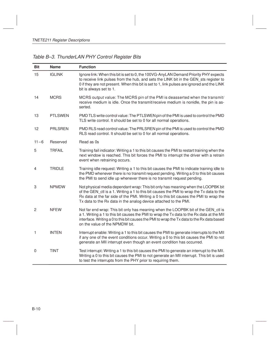
Trfail Tridle Npmdw Nfew Inten Tint
Iglink Mcrs Ptlswen Prlsren
Table B±3. ThunderLAN PHY Control Register Bits
Lstate
Mint Phok Config Retrain Lstate Trfrto Rtridl Lrcv Lsil
Table B±4. ThunderLAN PHY Status Register Bits
Retrain
Lrcv
Trfrto
Inten bit is also set, this causes an MII interrupt
Rtridl
TNETE100PM/TNETE110PM