MA-1650-4 Series
Page
STAND-ALONE Level OPERATOR’S Guide
Table of Contents
Cigarette and Alcoholic Beverage Entry
Registering Procedure and Print Format
Urgent PLU Maintenance
Other Income Department ENTRY, Other Income PLU Entry
Sale Finalization by EBT
Selective Itemizer SI Status Modification
Food Stampable Total READ, Food Stamp Tendering
Sale Finalization by EFT Electronic Fund Transfer
Paper Roll Replacement and Other Maintenance Operations
To OUR Customers
To OUR Customers
Unpacking
Unpacking
Appearance and Nomenclature
Appearance and Nomenclature
Mode Selector Keys
Mode Lock and Mode Selector Keys
Mode Lock
Mode Lock and Mode Selector Keys
DPT RPT
Display
Amount
Display
Mode Indications Lock Mode
Digit Range for Various Sales Items REG, MGR
Key Sequence or Operation Procedure Error
Error Messages in any mode except Lock
Error Message Cause of the Error Standard Setting
No code has been entered where it is compulsory
Numeric Display
Triangular Lamps
Status Lamps
REG
Outline of Preparation Procedure Before Operating the ECR
Outline of Preparation Procedure Before Operating the ECR
SET MGR
Turn the Mode Lock to the REG position with power on
Installing the Receipt/Journal Roll
Installing the Receipt Roll
MGR REG
Outline of Preparation Procedure Before Operating the ECR
Installing the Journal Roll
Setting the Ribbon Cassette
LOG/RECEIPT
Cashier Signing or Cashier KEY Operations
Code Entry Method
When Signed-OUT
Mode Changes With Signing Operations
When Signed-ON or Signed-IN
When Signed-OFF
Signing Operation Receipt Print Format Samples
Cashier KEY Method Hardware Option
Push-stay Cashier Locks and Keys
PUSH-ON
Cashier KEY Method CLK Keys
PUSH-AND-LOCK
Operation for Training Mode END
Training Mode Start and END
Entries in Training Mode
Operation for Training Modes Start
Training Mode Receipt Format
Receipt issued in Training Mode
Keyboard Layout
Card CHK DP#
PR Open Open
Pick UP BAL Code Open SI 1/M, SI 1/TL
Function 10 Read Tare 2 Tare 3 Comment
Functions of Each KEY
PR Open
AMT
Open
LC Open
AT/TL
ALL
Txbl
CHK Check
Code
Pick UP
BAL
SI1/TL SI2/TL SI/M
FS/M
TAX
Fstl
GST/M
Auth Store
PLU Preset-code Keys
Offline
For PLU
Condition Setting to Start Transaction Entries
Registering Procedure and Print Format
Registering Procedure and Print Format
Mode Lock Insert the REG key and set it to the REG position
Table of Contents
LOG/RECEIPT
RECEIPT-ISSUE/NON-ISSUE Selection
Store Message Display
Must be operated outside a sale
Loan
Drawer opens and a No-sale receipt is issued
NO-SALE
Receipt Print Format
Department Entry
Preset Dept
PR Open or Open Price Preset Dept Dept Code DP# Price AMT
Gasoline Entry
PLU Entry through Barcode Scanner
Price PLU Preset-Code Key of Preset-PLU
PLU Entry Manual PLU Code Entry
Preset-Dept Code DP# Price AMT RPT
Preset Dept Same Dept or RPT
Preset-price Open Repeat
Repeat Entry
Quantity Extension Multiplication for DEPTs/PLUs
Quantity @/FOR Preset Dept
Quantity @/FOR Price PLU Preset-Code Key of Open-PLU
Quantity @/FOR Price Open Dept
Preset PLU
Preset Department
Preset-price Open
PLU Preset-code Key
HI-CONE PLUs
Preset PLU 1 @/FOR
Whole Package Price PLU Preset-code Key
To enter Whole Package Quantity all the items packed
Operation Examples of HI-CONE PLUs
$0.68 $1.00 ÷ 3 = 33.33 ... rounded up to $0.34 ... x
Mix & Match M &M Function of Split-Price PLUs
Operation Examples of Mix & Match Functions
$1.00 Whole Package Price
Pack PLU Code PLU Pack PLU Preset-Code Key of Preset-PLU
Price Shift Entry for Split-Price PLUs
Whole package PLU No
Pack 1 PLU
PLU
@/FOR 1 PLU
3rd Price 1 PLU
Triple Multiplication
SUB-LINK Department Entry
SINGLE-ITEM Department or SINGLE-ITEM PLU Entry
Other Income Department ENTRY, Other Income PLU Entry
SUB-LINK PLU Entry
Urgent PLU Maintenance
Code Error
PLU ADD
RTN Mdse
Returned Merchandise
Bottle Return
@/FOR Unit Amount BTL RTN
Store Coupon
Dollar Discount
Percent DISCOUNT, Percent Charge
STR CPN
Void
Vendor Coupon
Item Correct
Item Corr
Allowed any time during a sale or transaction
ALL Void
NON-ADD Number Print
Number #
Scale Entry
Unit Price Open Dept
Selective Itemizer SI Status Modification
Tare Weight Tare Tare 2 Rate Tare
Listing Capacity Open
RTN Mdse for Return
Irregular Tax Amount to be Added TAX Receipt Print Format
TAX Status or Food Stamp Status Modification
Taxable Total Read and Subtotal Print
Txbl TL
Selective Itemizer SI Total Read
PLU Preset Price Read
Read PLU Code PLU Read PLU Preset-Code Key
TAX Calculation and Print
TAX Exemption
Food Stampable Total READ, Food Stamp Tendering
Txbl TL
Sale Finalization by Media Keys
MULTI-TENDERING
CHK TND
Company Code Card No. Chg ... Check & Credit Card
Split Tendering
Check & Cash
Chg ... Check, Cash, & Charge
Display
Entry for customer’s receipt 1st Receipt
FS TL/TEND
Entry for store’s receipt 2nd Receipt
2nd Receipt Print Format
Sale Finalization by EFT Electronic Fund Transfer
1st Receipt Print Format
EFT T/M
Credit 1 Card, Credit 2 Card and Check Card
ECR
Debit Card and EBT Cash Card
ECR EFT T/M
EBT Food Stamp Card Food Stamp Payment Type
10-33
Enter PIN #
EFT Media Key
FS Tend EFT
Confirm Amount
Authorization Code
Mode Lock REG, MGR
CUR1
Sale Paid in Foreign Currencies
Check , Debit
Amount Tendered Foreign Currency
Fraction process method is fixed to Round OFF
NO-SALE Exchange from Foreign Currency to Domestic Currency
NO-SALE Exchange from Domestic Currency to Foreign Currency
Amount to be paid out PO
RECEIVED-ON-ACCOUNT
PAID-OUT
HOLD/RECALL
Hold & Recall
Sales item entries
Operate sale item entries
Credit Card No. Check
Card CHK
Itemized Type Total-only Type
Receipt POST-ISSUE
Programmable options
Charge Posting Previous Balance Manual Entry Type
Txbl TL Chg
See Receipt 1 below
PB+
Dept
AT/TL See Receipt 2 below
Charge Posting Customer File Type Check Track Memory Option
New Customer File Code Code Open
1000 AT/TL
Pick UP BAL
498 R/A
See Receipt 2 below
00 DP1 ST AT/TL Function key
Function KEY Entry
Validation Print
Validate
Validation Print
Endorsement Print
Receipt Print
Printed on Remote Slip Printer
Print of a message using character code entry
Comment Print
Printed on Receipt/Journal Printer
Remote Slip Printer hardware option Operation
Program Options Relating to Remote Slip Control
Invoice Print Format
10-50
When a Power Failure Occurs
Charge Posting Sale File Print Format PB Manual Entry Type
During a
Outside a
Sale
For further details, refer to Chapter
Journal and Receipt PAPER-END Detector
Journal and Receipt PAPER-END Detector
ECR Printer Motor Lock Detector
ECR Printer Motor Lock Detector
Remote Slip Printer Motor Lock Detector
Remote Slip Printer Motor Lock Detector
Printer Guide Open Detector
Printer Guide Open Detector
Replacing the Receipt Roll
Paper Roll Replacement and Other Maintenance Operations
Paper Roll Replacement and Other Maintenance Operations
It may cause paper jamming
Replacing the Journal Roll
Replacing the Ribbon Cassette
Replenishing Ink to the Store Name Stamp
Manual Drawer Releasing
Removing the Drawer
Locking
Unlock the cover using the key, and lift the front end 15-6
CDC Cash Drawer Cover Option Lock
Unlocking
Specifications
Specifications
STAND-ALONE Level MANAGER’S Guide
Basic KEY Functions and Keyboard Variations
Charge Posting with Customer File
General Notes on Report Takings
Cashier Code and Name Programming Submode
Foreign Currency Exchange Rate Setting
Customer File Code Check Track NO. and Name Setting
PLU Unit Price Dollar DISCOUNT/EXTRA Charge Amount Setting
CASHIER’S Operations
Daily Operation Flow
Daily Operation Flow
Sign-OFFor Cashier Key to OFF
Manager Intervention
Manager Intervention
Items Programmed to Require Manager Interventions
STR CPN BTL RTN
Doll Disc
VND CPN
RTN Mdse Void
Negative Amount KEY Amount Limit Read
Other Operations Requiring Manager Interventions
Function Keys Amount Limit Read
Pick UP Operation
MANAGER’S OWN Operations in MGR Mode
MANAGER’S OWN Operations in MGR Mode
Or VND CPN
Cashier Code and Name Read
Enforced SIGN-OFF of a Cashier Code Entry Method
LOG/RECEIPT or LOG
Operations in Mode
Operations in Mode
Ordinary Operations in Mode
Receipt Issued in REG or MGR Mode
Receipt AT Return
Entries of the purchased items*** Txbl TL Chg
Receipt AT Purchase
NO-SALE NS AUTO-SCALE described
Scale Item Entry in Mode
Prohibitive Operations in Mode
NO-SALE Cashing of Cheque or Other NON-CASH Medias
Daily Reports
Read X and Reset Z Reports
Read X and Reset Z Reports
Then 4 # AT/TL
13 AT/TL
AT/TL to end
11 AT/TL
15 AT/TL
206 AT/TL
GT Reports -- to be taken on weekly or monthly basis
Then 204 # AT/TL
208 AT/TL
Report Name Available Reports
Combination Reports
General Notes on Report Takings
GTX GTZ
Reset Report Format Sample
Financial Read or Reset Daily or GT
Read Report Relevant Reset Report
To be
Financial Read or Reset
Installed
Cashier Read or Reset Daily or GT
Reset Report Sample
Daily Salesperson Read or Reset
Credit Card Company Sales Read or Reset Daily or GT
Daily ALL Media Sales Total and CASH-IN-DRAWER Read
Department Group Read Daily or GT
Minor Groups
Daily Media Sales and IN-DRAWER Total Read
Daily Hourly Range Read or Reset
Read only Mode Lock X, enter 9, depress AT/TL
Department Read or Reset
Individual Department Read Daily or GT
All Department Read or Reset Daily or GT
DP ALL
Individual PLU Read Daily or GT
PLU PLU Sales Data Read or Reset
Zone PLU Read or Reset Daily or GT
PLUs of zero sale will be skipped
Prints data in order from lower to larger numbered PLU Code
Zone Files Read or Reset
Customer File Read or Reset
All Files with balance remaining Read or Reset
Individual Files Read
Cust Cred
PLU Group Sales Read or Reset Daily or GT
GT Reports
Table of Programming Operations
Programming Operations
Programming Operations
Submode No
AT/TL Used to end the entire program Submode sequence
Basic Key Functions
Keyboard Variations in Programming operations
Character Entries
Character Code Standard Characters Column Code Row
Character Setting Operations
Character Code Entry Method
407 # 502 # 415 # 505 # 500 #
Direct Character Entry Method
All Double-sized Declaration
Sftlock Omato AT/TL
Space
Line No. ST
Mode Lock SET
Condition Required for Programming Operations
Character Entries
Rubber Stamp
405 # E 403 # C
Condition Operation
Cashier Code and Name Programming Submode
Programming
CLK key
Depress AT/TL to end this submode
Deletion
Item Corr Cashier Code NS AT/TL or
Following case Any time outside a sale
PLU Table Programming Submode
Programming or Changing
Address No Description of Programming Contents
Address No Description of Programming Contents
Address No Description of Programming Contents
HEAD-LINK PLU SUB-LINK PLU
Remarks
Additional Notes
Ex. To program the following PLUs
KEY Operation is on the next
# Link-PLU Table No
90601 PLU
10 ST
101301 PLU
@/FOR Item Corr PLU Code PLU or
To delete a PLU with sales data of not zero After PLU Reset
Individual PLU Deletion Barcode Scanning
All PLU Deletion
Any time outside a sale except the following case
After PLU Reset
PLU Programmed Data Copying
Digit Length of PLU Codes
Coding With Linked Department Code
Using Barcodes source-marking EAN or UPC barcodes
Coding Methods
Coding With Type ID for Each Digit
Hour Minute
Time Setting or Adjustment Submode
Date Setting or Adjustment Submode
Day-of-Week Code Month
CHK TND
Amount Limit Setting for Function Keys Submode
Day-of-week is programmable not to be printed on receipts
11 ST
Deletion of All Customer File Codes
Customer File Code Check Track NO. and Name Setting Submode
Deletion of Individual Customer File Codes
Void AT/TL
ST Customer File Code 408 # 405 # 412 #
Code Name James Haily Helen Reed
Name James Haily
405 # 414 # # 502 # 405 # 405 # 404 # ST
ST AT/TL
Salesperson Code and Name Programming Submode
20 @/FOR
Code Name
Item Corr 3 ST AT/TL
LINK-PLU Table Programming Submode
20 @/FOR Item Corr Salesperson Code ST or
25 @/FOR
ST 101301 PLU AT/TL
Tare Table and General Unit Weight Setting Submode
Deletion of Link-PLU Tables
25 @/FOR Item Corr Link-PLU Table No. ST or
27 @/FOR
PLU PRESET-CODE KEY Setting Submode
ST 13 # 2 AT/TL
KEY
PK-2 Keyboard
138 141 101 106 113 120 127
136 139 105 111 118 125
137 140 100 112 119 126
142 102 107 114 121
31 @/FOR
Any time outside a sale Mode Lock SET Message Line No. ST
Display Message Programming Submode
Character Entries ST
Operation Mode Lock SET, enter 31, depress @/FOR
KEY Code and KEY Table
Negative Amount KEY Limit Amount Setting Submode
35 @/FOR
35 @/FOR ST 1000 #
RTN Mdse Amount #
Department Preset Price Setting or Changing
40 @/FOR
ST RTN Mdse 150 # 10 ST 200 # AT/TL
New Preset Price #
Setting or Changing Preset Price
Mode Lock SET Barcode Scanning PLU Code PLU
By the second operation pattern 13 DP# 140 # 14 DP# 210 #
65 #
155 #
120501 PLU
PLU 6 ST 125 # AT/TL
SI1/TL or SI/TL
23 %+ and %- Preset Rate Setting
Preset Rate Setting for Selective Itemizers SI1 and SI2
SI2/TL
ST1/TL
Ex. To set 7% as SI 1 preset % rate Mode Lock SET
Selective Itemizer Functions and Applications
Receipt/Journal Print
Example 2 With option SI Special Discount
Foreign Currency Exchange Rate Setting
Foreign Currency Exchange Rate Calculation
CUR
Domestic
Resetting a Foreign Currency Rate Once Set
Ex. To set three foreign currency rates
Type 3 TAX 1 % Rate only
TAX Table Programming
Type 2 TAX 1 Combination of NON-CYCLIC Breaks and % Rate
TX1/M
Ex TAX 2 Combination of NON-CYCLIC Breaks and % Rate
TX2/M 29 TX2/M 59 TX2/M 84 TX2/M 112 TX2/M
TX3/M
GST Rate Setting
STORE/REGISTER NO. Setting
12 GST/M
STORE/REGISTER NO. Setting
1 AT/TL
Verification of Programmed Data
Verification of Programmed Data
0 AT/TL
Depress Txbl TL
Tax Calculation Test
Enter any amount
Bar Code Type Table
BAR Code System for Each Model
BAR Code System for Each Model
S Level OPERATOR’S Guide
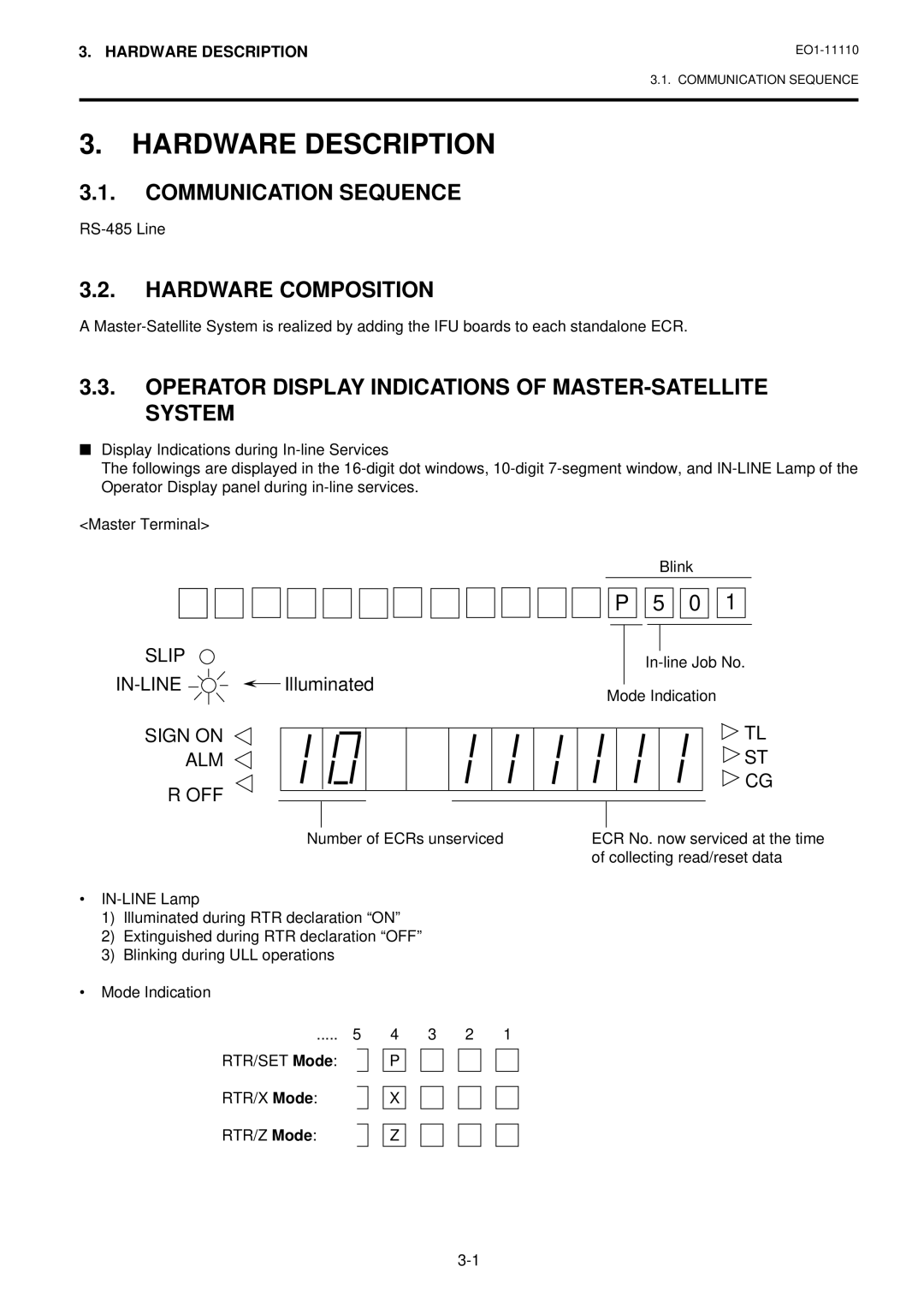
Operator Display Indications of MASTER-SATELLITE System
Introduction
Introduction
System Configuration
System Configuration
Hardware Composition
Hardware Description
Communication Sequence
Operator Display Indications of MASTER-SATELLITE System
IRC Connect ERR
IN-LINE Error Code and Message Table
Occupy
Master is Busy
RTR
Additional Function KEY and Registering Procedure
Additional Function KEY and Registering Procedure
RTR Register-to-Register Declaration Key RTR
S Level MANAGER’S Guide
Verification of Programmed Data Related to
Department and PLU Maintenance
Department Preset Price Setting or Changing with DLL
Other Operations Relating to IN-LINE Service
Sign ON, Sale Entries, Sign OFF
Turn on the power of every ECR in the in-line system
Master Terminal
Read X Report Takings on Individual Terminals
Consolidated Report Data Read
In-line Reset Report Takings on
Department and PLU Maintenance Chapter
Programming Operations Chapter
Terminal Open Check
Operations Before IN-LINE Service
Operations Before IN-LINE Service
80 AT/TL
Register No. #
Terminal Designation
To be operated on the Master Terminal only
# 3003 # AT/TL
Terminal Condition Check
81 AT/TL
Reservation
Reservation
Reservation Function
To be on next
624 AT/TL
724 AT/TL
Customer File Reports
All Files Reset Version 1.7 or after 615
Report Reservation Print Format
For Check Track Memory type only All Files Read 615
Enforced Clear of Communication Buffer
Operations Relative to Reservation
Read of Information Already Copied in Communication Buffer
96 AT/TL
Terminal Reports
Read and Reset Reports
Read and Reset Reports
Conditions required on terminals for In-line Report takings
IN-LINE Report Command Executions
IN-LINE Reports
Lock Positions Required
Chapter
Operation Flow of IN-LINE Read or Reset Reports
Refer to
Refer to the following pages
Table of IN-LINE Report Operations
# → PLU Code PLU → ST AT/TL
Process Reports Note on the next
# → Dept or Code DP# → ST
13 # → 0 AT/TL
# →
Customer File Read
# → File Code @/FOR → AT/TL
Process Reports and Base Report Data
IN-LINE Report Print Format
IN-LINE Report Type
Copy of GT reset data has completed
Reset Report Collection Indication
Copy of daily reset data has completed
Read Report Collection Indication
Enforced Clear of Hold Condition on Individual Terminals
Operations After IN-LINE Report Takings
Consolidated Report Data Read Reprint
90 AT/TL
Programming Operations Common with Standalone ECR Level
Programming JOB List
69 @/FOR
Mode Lock SET and IN-LINE Lamp illuminated
Programming Operations Added for IN-LINE Terminals
In-line ID No. ST Register No. #
177
Terminal ID Setting Submode
77 @/FOR Terminal ID No. AT/TL
DLL Down-Line-Loading Operations
DLL JOB List
Satellite Terminals Journal
Print Format of DLL Operations
Master Terminal Receipt
Table of Department and PLU Maintenance Operations
Department and PLU Maintenance
Department and PLU Maintenance
Mode ..... Submode
13 ST
PLU Table ADDITION/CHANGE/DELETION with DLL Submode
63 @/FOR
Item Corr PLU Code PLU ST
Mode Lock SET and IN-LINE Lamp illuminated New Preset Price
Programming, or report taking operations
Any time outside a sale for Master or Satellite
New Whole Package Quantity ST
PLU Price Change with DLL Submode
73 @/FOR PLU Code PLU
PLU Inquiries
PLU Urgent Maintenance
Inquiries
Customer File Check Track Inquiries
Cashier Occupy Inquiries
Cashier Cancel Inquires Occupy Cancel
Credit Card No. Inquiries to the Negative Check File
Only When the Backup Master is Connected
Backup Function
Backup Function
Procedure Changing Program Data DLL from the PC
900 AT/TL
Data Capture Function
Data Capture Funciton
Master and Backup Master Alternation
Master and Backup Master Alternation
Error Display
Transmission Error
Cause of Error
IRC Connect ERR
→ ST Stops the inquiry, printing on journal ** X → ST
Error Canceling Process
AT/TL Performs re-sending to the other station
Time OUT
Other Operations Relating to IN-LINE Service
Other Operations Relating to IN-LINE Service
Incomplete Ending
Suspending
Retry
Description
Cancel
Status Print Format
Page
EO1-11110