4 Replacement Procedures | 4.1 General |
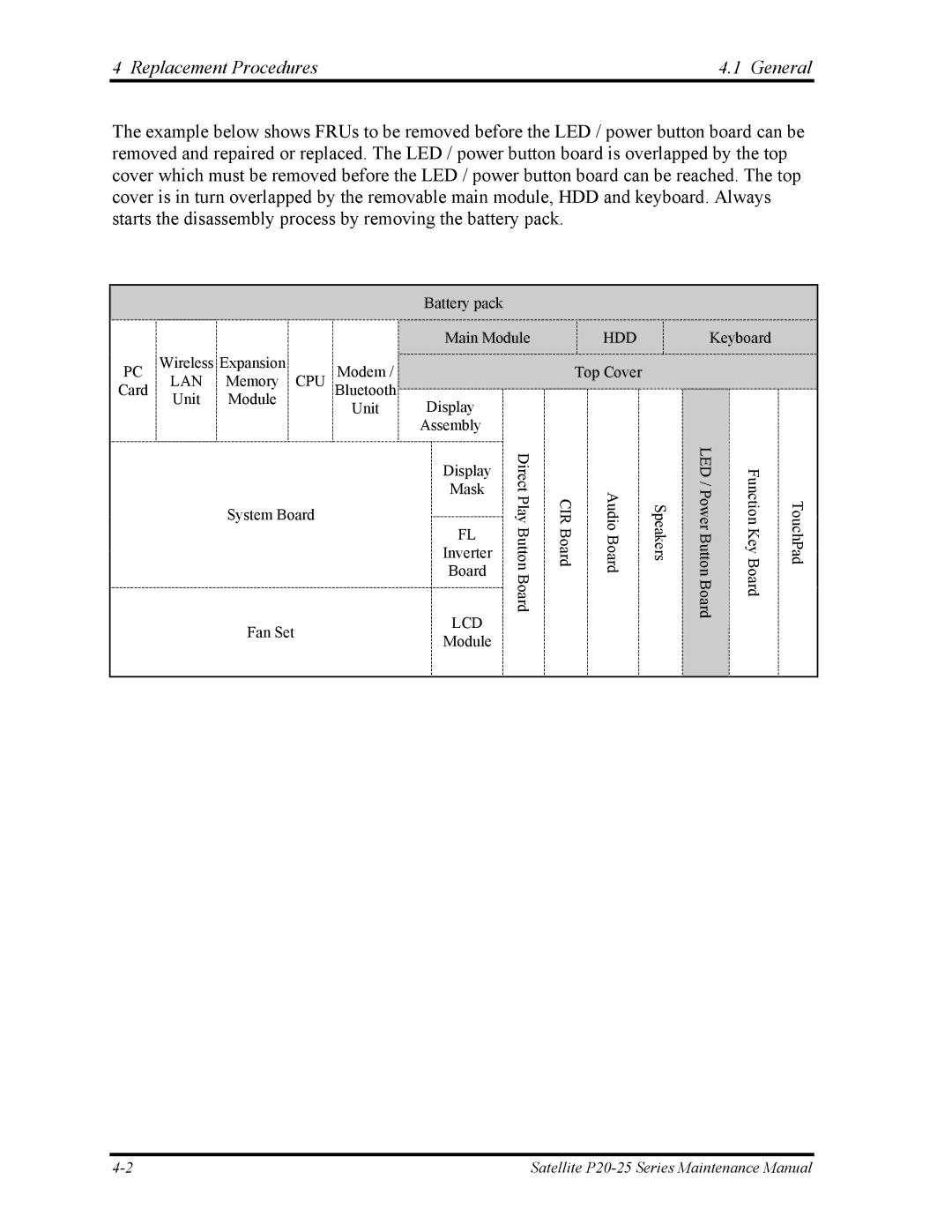
The example below shows FRUs to be removed before the LED / power button board can be removed and repaired or replaced. The LED / power button board is overlapped by the top cover which must be removed before the LED / power button board can be reached. The top cover is in turn overlapped by the removable main module, HDD and keyboard. Always starts the disassembly process by removing the battery pack.
Battery pack
|
|
|
| Main Module | |
PC | Wireless Expansion | Modem / |
|
| |
LAN | Memory CPU |
|
| ||
Card | Unit | Module | Bluetooth | Display |
|
| Unit |
| |||
|
|
|
| ||
|
|
|
| Assembly | Direct |
|
|
|
| Display | |
|
|
|
|
| |
|
|
|
| Mask | Play |
|
| System Board |
| FL | |
|
|
|
| Button | |
|
|
|
| Inverter | |
|
|
|
|
| |
|
|
|
| Board | Board |
|
|
|
|
| |
Fan Set | LCD | |
Module | ||
|
HDD Keyboard
Top Cover
CIR Board | Audio Board | Speakers | LED / Power Button Board | Function Key Board | TouchPad |
|
|
|
|
|
|
Satellite |