4.20 System Board | 4 Replacement Procedures |
3.Remove the keyboard, HDD, main module, CPU, modem or Bluetooth unit, expansion memory cards, wireless LAN cards, PC card(s), top cover and display assembly.
4.Remove nine M2.5⋅4 screws securing the low I/O cover (five from the top, two from the rear, and two from the base).
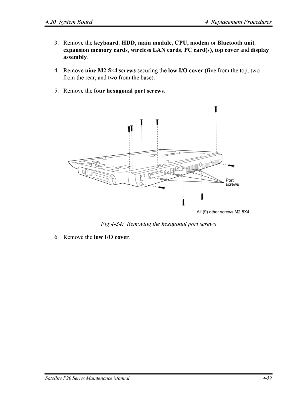
5.Remove the four hexagonal port screws.
Fig 4-34: Removing the hexagonal port screws
6.Remove the low I/O cover.
Satellite P20 Series Maintenance Manual |