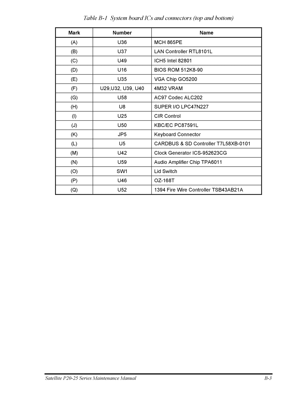
Table B-1 System board ICs and connectors (top and bottom)
Mark | Number | Name |
|
|
|
(A) | U36 | MCH 865PE |
|
|
|
(B) | U37 | LAN Controller RTL8101L |
|
|
|
(C) | U49 | ICH5 Intel 82801 |
|
|
|
(D) | U16 | BIOS ROM |
|
|
|
(E) | U35 | VGA Chip GO5200 |
|
|
|
(F) | U29,U32, U39, U40 | 4M32 VRAM |
|
|
|
(G) | U58 | AC97 Codec ALC202 |
|
|
|
(H) | U8 | SUPER I/O LPC47N227 |
|
|
|
(I) | U25 | CIR Control |
|
|
|
(J) | U50 | KBC/EC PC87591L |
|
|
|
(K) | JP5 | Keyboard Connector |
|
|
|
(L) | U5 | CARDBUS & SD Controller |
|
|
|
(M) | U42 | Clock Generator |
|
|
|
(N) | U59 | Audio Amplifier Chip TPA6011 |
|
|
|
(O) | SW1 | Lid Switch |
|
|
|
(P) | U46 | |
|
|
|
(Q) | U52 | 1394 Fire Wire Controller TSB43AB21A |
|
|
|
Satellite |