INDOOR UNIT <DIGITAL INVERTER>
OUTDOOR UNIT <DIGITAL INVERTER>
FILE NO. A07-009
SERVICE MANUAL
SAFETY CAUTION
CONTENTS
SPECIFICATIONS
WIRING DIAGRAM
7. INDOOR CONTROL CIRCUIT
6. REFRIGERANT R410A
Explanation of indications
DANGER
Explanation of illustrated marks
Confirmation of warning label on the main unit
– 5 –
– 6 –
2.Cautions on Installation/Service
1. Safety Caution Concerned to New Refrigerant
• New Refrigerant R410A
3.Pipe Materials
General tools Conventional tools can be used
4.Tools
1-1.Indoor Unit
1. SPECIFICATIONS
– 9 –
1-1-1.High Static Duct Type <Single type>
Indoor unit
– 10 –
SM1604UT-E
Outdoor unit
<Twin type>
– 12 –
<Triple
type>
1-1-3.Concealed Duct Type <Twin type>
– 13 –
type>
<Triple
1-1-4.Under Ceiling Type <Twin type>
– 15 –
– 16 –
<Triple
type>
1-1-5.High Wall Type Twin type
– 18 –
<Triple
type>
1-1-6.Compact 4-wayCassette 600 × 600 Type
Triple
type
– 20 –
1-1-7.Slim Duct Type
<Triple
type>
1-2.Outdoor Unit
– 21 –
RAV-SM1603ATZZG-E
• Operation characteristic curve
1-3.Operation Characteristic Curve
– 22 –
RAV-SM1603AT-E, RAV-SM1603ATZ-E, RAV-SM1603ATZG-E
2-1.Indoor Unit
2. CONSTRUCTION VIEWS EXTERNAL VIEWS
Service work space
– 23 –
Outdoor Unit
SM1603ATZ-E
SM1603AT-E,RAV
RBC-TWP30E2, RBC-TWP50E2Simultaneous Twin
– 25 –
RBC-TRP100ESimultaneous Triple
<Gas side>
Gas side socket
Liquid side socket
3-1.Indoor Unit
3. SYSTEMATIC REFRIGERATING CYCLE DIAGRAM
Dimension table
Capillary tube specifications
•Single type
3-2.Outdoor Unit
Systematic Diagram of Refrigerating Cycle
– 29 –
RAV-SM1603AT-E, RAV-SM1603ATZ-E, RAV-SM1603ATZG-E
4-1.Indoor Unit
4. WIRING DIAGRAM
– 30 –
RAV-SM1403DT-A, RAV-SM1603DT-A
• Twin type
• Single type
• Triple type
– 31 –
4-2.Outdoor Unit
– 32 –
RAV-SM1603AT-E, RAV-SM1603ATZ-E, RAV-SM1603ATZG-E
REQUIREMENT
4-3.Fan Characteristics
nWire connection change of fan motor
– 33 –
5-1.Indoor Unit
5. SPECIFICATIONS OF ELECTRICAL PARTS
5-2.Outdoor Unit
– 34 –
6-2.Refrigerant Piping Installation
6-1.Safety During Installation/Servicing
6. REFRIGERANT R410A
6-2-1.Piping Materials and Joints Used
– 36 –
6-2-2.Processing of Piping Materials
Table 6-2-1Thicknesses of annealed copper pipes
Thickness mm
Flare and flare nut dimensions for R410A
Fig. 6-2-1Flare processing dimensions
Flare and flare nut dimensions for R22
Table
Nominal
– 38 –
Outer diameter
Tightening torque
6-4.Recharging of Refrigerant
6-3.Tools
Fig. 6-4-1Configuration of refrigerant charging
6-3-1.Required Tools
6-5-2.Flux 1.Reason why flux is necessary
6-5.Brazing of Pipes
6-5-1.Materials for Brazing
1.Silver brazing filler
3.Types of flux
2.Characteristics required for flux
6-5-3.Brazing
1.Brazing method to prevent oxidation
6-6-4.Curing of Pipes
6-6.Instructions for Re-usePiping of R22 or R407C
Page
6-6-6.Handling of Existing Pipe
Cautions for using existing pipe
– 44 –
RAV-SP1404AT-E, RAV-SP1404ATZ-E, RAV-SP1404ATZG-E
Procedure
6-6-7.Recovery Method of Refrigerant
Procedure
DANGER
n Twin system
6-7.Tolerance of Pipe Length and Pipe Head
Indoor unit A Indoor unit B
Outdoor unit
– 47 –
n Triple system
Indoor unit A
Indoor unit C
nTwin system
6-8.Additional Refrigerant Amount
– 48 –
Indoor unit A Indoor unit B
– 49 –
nTriple system
Indoor unit A
Indoor unit C
nTwin system
6-9.Piping Materials and Sizes
nTriple system
– 50 –
NO GOOG
OKOK
6-10.Branch Pipe
6-11.Distributor
7-1-1.Connection of Main Sub Remote Controller
7-1.Indoor Controller Block Diagram
7. INDOOR CONTROL CIRCUIT
– 52 –
Outline of specifications
7-2.Control Specifications
– 53 –
Item
– 54 –
Outline of specifications
Item
Remarks
– 55 –
Outline of specifications
Item
Remarks
K 2 J
Outline of specifications
– 56 –
Remarks
Setup at shipment
Outline of specifications
– 57 –
Item
Outline of specifications
– 58 –
Item
∗This option is not provided to oversea models
– 59 –
– 60 –
7-4.Indoor Print Circuit Board
<MCC-1403>
RAV-SM1403DT-A, RAV-SM1603DT-A
7-5.Outdoor Print Circuit Board
Noise filter P.C. board <MCC-1551>
– 62 –
<MCC-1531>
– 63 –
REQUIREMENT
8-1.Outdoor Controls
8-1-1.Outline of Main Controls
1.Pulse Motor Valve PMV control
Operation with WE
4. Outdoor fan control
– 65 –
Allocations of fan tap revolutions rpm
5.Coil heating control
REQUIREMENT
– 66 –
In trouble of TO sensor
7.High pressure restraint TE control
6.Short intermittent operation preventive control
8.Over-currentprotective control
9.Current release value shift control
Start of heating operation
10. Defrost control
9-1.Summary of Troubleshooting
9. INDOOR UNIT TROUBLESHOOTING
1. Before troubleshooting
2. Troubleshooting procedure
9-2-1.Check Code List Indoor
9-2.Troubleshooting
– 71 –
Error mode detected by indoor unit
– 72 –
E09 error
Check code E01 error
E04 error
E10 error
– 74 –
E08, L03, L07, L08 error
E18 error
L09 error
– 75 –
L30 error
L20 error
P30 error Central controller
– 76 –
P10 error
F10 error
– 77 –
P19 error
Exchange to cooling cycle
Exchange to heating cycle
F02 error
F01 error
– 79 –
– 80 –
C06 error TCC-LINKcentral controller
F29 error
E03 error Master indoor unit
P31 error Follower indoor unit
– 81 –
TA, TC, TCJ, TE, TS, TO sensors
Temperature sensor
TD, TL sensors
TA, TC, TCJ, TE, TS, TO sensors
10-1.Summary of Troubleshooting
10. OUTDOOR UNIT TROUBLESHOOTING
1. Before troubleshooting
2. Troubleshooting procedure
1. Before troubleshooting
2.Troubleshooting procedure
<Wireless remote controller type>
– 84 –
10-2.Troubleshooting
10-2-1.Outline of Judgment
– 85 –
Lamp indication
Check code
Cause of trouble occurrence
<Display on wired remote controller>
New Check Code
<Display on wireless sensor>
10-2-2.Others Other than Check Code
– 88 –
10-2-3.Check Code List Outdoor
– 89 –
– 90 –
Error mode detected by indoor unit
– 91 –
Operation. of diagnostic function
Judgment and measures
Cause of operation
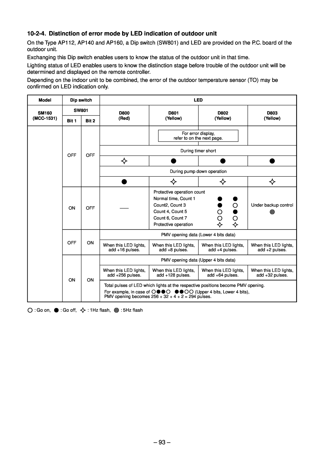
– 92 –
Error mode detected by outdoor unit
– 93 –
Page
Check code E01 error
E09 error
– 95 –
– 96 –
E04 error
E18 error
E10 error
E08, L03, L07, L08 error
– 97 –
L20 error
L09 error
L30 error
– 98 –
P01 error
b7 error Central controller
P10 error
F10 error
– 100 –
– 101 –
P12 error
CN301, ∗ CN303 CN300
P22 error
– 102 –
RAV-SM160AT-E
P19 error
F02 error
103
F01 error
P26 error
– 104 –
F06 error
P29 error
P04 error
105
L29 error
F08 error
H02 error
– 106 –
P03 error
H01 error
– 107 –
– 108 –
P04 error
– 109 –
97 error Central controller
F29 error / 12 error
E03 error Master indoor unit
P31 error Sub indoor unit
– 110 –
TA sensor
– 111 –
TC, TCJ sensor
Caracteristics-1
Page
1 Setting data read out from EEPROM
– 113 –
CODE No. required at least
3 6 5
3 Writing the setting data to EEPROM
– 114 –
Step
Table
115
Table 2. Type: CODE No.
Table 3. Indoor unit capacity: CODE No.
12-1.Indoor Unit
12. SETUP AT LOCAL SITE AND OTHERS
12-1-1.Test Run Setup on Remote Controller
<Wired remote controller>
4 5 2
3 6 1
1 2 3 4 5 6 END
1.D02 Red
118
Contents
Function selection item No. DN list
At shipment from factory
Wired remote controller
Setup method
– 119 –
Operation
<Contents>
2 4 1
<Procedure>
call the service monitor mode
<Contents>
nCalling of error history
Procedure
4 seconds or more to call the service check mode
which receives power feed from outdoor unit>
nIndoor unit power-ONsequence
<Automatic address judgment>
<By indoor unit
2. Microprocessor block diagram
12-2.Setup at Local Site / Others
3. TCC-LINKwiring connection
1. Function
4. Wiring specifications
5. P.C. board switch SW01 setup
– 124 –
7. Address setup
6. External view of P.C. board assembly
12-3.How to Set up Central Control Address Number
1 2 3 4
Push UNIT LOUVER button for 4 seconds or more
– 126 –
13. ADDRESS SETUP
13-1.Address Setup Procedure
– 127 –
13-2-1.System Configuration
13-2.Address Setup & Group Control
– 128 –
<Terminology>
Example
– 129 –
Change is necessary
2, 5,
3, 6, 9 4
1 2 3 4 5 6 7 8 9 10 11 END
1 2 3 END
1 2 END
nConfirmation of indoor unit No. position
<Procedure>
14. DETACHMENTS
2. How to replace the parts
14-1.Indoor Unit REQUIREMENT
Work procedure
Work procedure
2. How to replace the parts Continued
– 134 –
Explanatory drawing
2. How to replace the parts Continued
Work procedure
– 135 –
Work procedure
4. How to replace the parts
REQUIREMENT
– 136 –
Work procedure
4. How to replace the parts Continued
– 137 –
Explanatory drawing
4. How to replace the parts Continued
5.Assembling work after replacing fan motor
Work procedure
– 138 –
6. How to replace the sensor
Work procedure
– 139 –
7. How to clean the drain port
6. How to replace the sensor Continued
Work procedure
Work procedure
– 141 –
14-2.Outdoor Unit
XREQUIREMENTX
XREQUIREMENTX
– 142 –
Procedure
Part name
CDB board
– 143 –
144
– 145 –
XCAUTIONX
XREQUIREMENTX
XREQUIREMENTX
– 146 –
XWARNINGX
– 147 –
X CAUTIONX
X CAUTIONX
2. Mounting of compressor
– 148 –
3. Vacuuming
4. Refrigerant charge
XREQUIREMENTX
149
XREQUIREMENTX
1. Detachment
15-1
15. EXPLODED VIEWS AND PARTS LIST
Indoor Unit
– 150 –
Location
151
Part No
Description
RAV-SM1403DT-A, RAV-SM1603DT-A
– 152 –
Location
Part No
15-2.Outdoor Unit
Location
154
Description
Model Name
716,
Check of Concentration Limit
WARNINGS ON REFRIGERANT LEAKAGE
TOSHIBA CARRIER CORPORATION