13. FAILURE DIAGNOSIS PROCEDURE
Model of N5SS chassis is equipped with self diagnosis func-
tion inside for trouble shooting.
13-1. Contents to be Confirmed by Customer
Table
| Contents of self diagnosis |
| Display items and actual operation |
|
|
| |
A. | DISPLAY OF FAILURE INFORMATION IN NO | Power indicator lamp blinks and picture does not come. | |
| PICTURE (Condition of display) |
|
|
1. | When power protection circuit operates; | 1. | Power indicator red lamp blinks. (0.5 seconds interval) |
2. | When | 2. | Power indicator red lamp blinks. (1 seconds interval) |
|
| If these indication appears, repairing work is required. | |
|
|
|
|
| Table |
|
| |
|
|
|
| |
Contents of self diagnosis |
| Display items and actual operation |
| |
|
|
|
| |
Contents of self diagnosis |
| Display items and actual operation |
| |
< Countermeasure in case that phonomenon always arises > |
|
|
| |
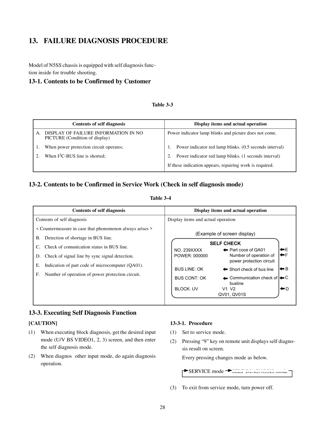
B. Detection of shortage in BUS line. |
| (Example of screen display) |
| |
|
|
|
| |
C. Check of comunication status in BUS line. |
|
| SELF CHECK |
|
| NO. 239XXXX | Part coce of QA01 | E | |
|
| |||
D. Check of signal line by sync signal detection. |
| POWER: 000000 | Number of operation of | F |
E. Indication of part code of microcomputer (QA01). |
|
| power protection circuit |
|
| BUS LINE: OK | Short check of bus line | B | |
F. Number of operation of power protection circuit. |
| |||
| BUS CONT: OK | Communication check of | C | |
|
| |||
|
|
| busline |
|
|
| BLOCK: UV | V1 V2 | D |
|
|
| QV01, QV01S |
|
|
|
|
|
|
13-3. Executing Self Diagnosis Function
[CAUTION]
(1)When executing block diagnosis, get the desired input mode (U/V BS VIDEO1, 2, 3) screen, and then enter the self diagnosis mode.
(2)When diagnos other input mode, do again diagnosis operation.
(1)Set to service mode.
(2)Pressing “9” key on remote unit displays self diagno- sis result on screen.
Every pressing changes mode as below.
![]() SERVICE mode
SERVICE mode ![]()
![]()
(3)To exit from service mode, turn power off.
28