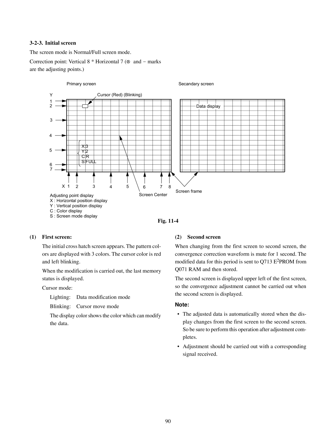
3-2-3. Initial screen
The screen mode is Normal/Full screen mode.
Correction point: Vertical 8 * Horizontal 7 (® and - marks are the adjusting points.)
Primary screen | Secandary screen |
Y |
|
| Cursor (Red) (Blinking) |
|
|
| |
1 |
|
|
|
|
|
|
|
2 |
|
|
|
|
|
|
|
3 |
|
|
|
|
|
|
|
4 |
|
|
|
|
|
|
|
5 |
| X:3 |
|
|
|
|
|
| Y:2 |
|
|
|
|
| |
|
| C:R |
|
|
|
|
|
6 |
| S:FULL |
|
|
|
|
|
|
|
|
|
|
|
| |
7 |
|
|
|
|
|
|
|
X 1 | 2 | 3 | 4 | 5 | 6 | 7 | 8 |
Adjusting point display | Screen Center |
X : Horizontal position display |
|
Y : Vertical position display |
|
C : Color display |
|
S : Screen mode display |
|
Data display
Screen frame
Fig.
(1) First screen: | (2) Second screen |
The initial cross hatch screen appears. The pattern col- ors are displayed with 3 colors. The cursor color is red and left blinking.
When the modification is carried out, the last memory status is displayed.
Cursor mode:
Lighting: Data modification mode
Blinking: Cursor move mode
The display color shows the color which can modify the data.
When changing from the first screen to second screen, the convergence correction waveform is mute for 1 second. The modified data for this period is sent to Q713 E2PROM from Q071 RAM and then stored.
The second screen is displayed upper left of the first screen, so the convergence adjustment cannot be carried out when the second screen is displayed.
Note:
•The adjusted data is automatically stored when the dis- play changes from the first screen to the second screen. So be sure to perform this operation after adjustment com- pletes.
•Adjustment should be carried out with a corresponding signal received.
90
