3-1. +35V Over Current Protection Circuit
The over current protection circuit cuts off the power supply relay when it detects abnormal current increased in the +35V power line due to failure of the vertical deflection circuit.
3-1-1. Theory of Operation
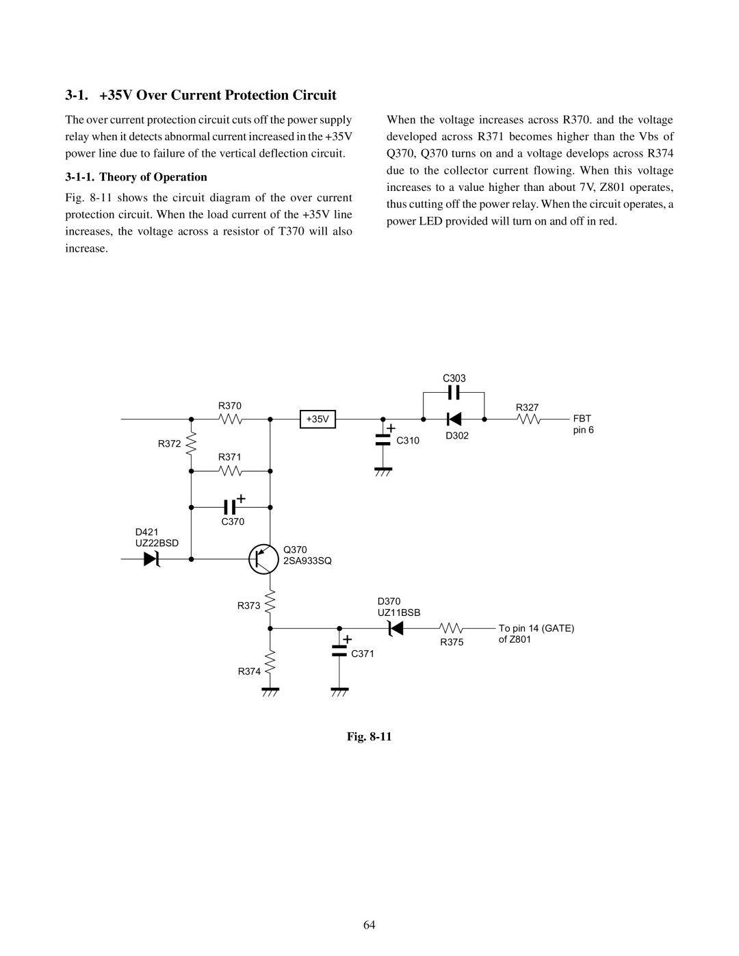
Fig. 8-11 shows the circuit diagram of the over current protection circuit. When the load current of the +35V line increases, the voltage across a resistor of T370 will also increase.
When the voltage increases across R370. and the voltage developed across R371 becomes higher than the Vbs of Q370, Q370 turns on and a voltage develops across R374 due to the collector current flowing. When this voltage increases to a value higher than about 7V, Z801 operates, thus cutting off the power relay. When the circuit operates, a power LED provided will turn on and off in red.
C303
| R370 |
|
|
|
| +35V |
|
R372 |
| C310 | D302 |
|
| ||
|
|
| |
| R371 |
|
|
| C370 |
|
|
D421 |
|
|
|
UZ22BSD |
| Q370 |
|
|
|
| |
|
| 2SA933SQ |
|
| R373 | D370 |
|
| UZ11BSB |
| |
|
|
| |
|
|
| R375 |
|
| C371 |
|
| R374 |
|
|
R327
FBT pin 6
To pin 14 (GATE) of Z801
Fig.
64