Amplitude Correction
To vary horizontal amplitude, it is necessary to vary a sawtooth wave current flowing into the deflection coil. These are two methods to vary the current; a method which varies LH by connecting a variable inductance L in series with the deflection yoke, and a method which varies power supply voltage (across
As the DPC circuits is used in the this chassis, the later method which varies the deflection yoke power supply volt- age by modifying the bus data is used.
4-1-2. Linearity Correction (LIN)
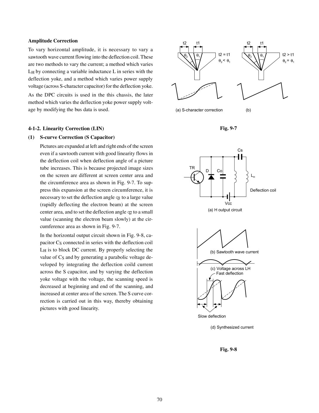
t2 | t1 |
| t2 | t1 |
|
θ2 | θ1 | t2 = t1 | θ2 | θ1 | t2 > t1 |
|
| θ2 < θ1 |
|
| θ2 = θ1 |
(a) | (b) |
Fig.
(1) |
Pictures are expanded at left and right ends of the screen |
even if a sawtooth current with good linearity flows in |
the deflection coil when deflection angle of a picture |
tube increases. This is because projected image sizes |
on the screen are different at screen center area and |
the circumference area as shown in Fig. |
press this expansion at the screen circumference, it is |
necessary to set the deflection angle q1 to a large value |
(rapidly deflecting the electron beam) at the screen |
center area, and to set the deflection angle q2 to a small |
value (scanning the electron beam slowly) at the cir- |
cumference area as shown in Fig. |
In the horizontal output circuit shown in Fig. |
pacitor CS connected in series with the deflection coil |
L is to block DC current. By properly selecting the |
TR
Cs
D Co
Vcc
(a) H output circuit
LH
Deflection coil
H |
value of CS and by generating a parabolic voltage de- |
veloped by integrating the deflection coild current |
across the S capacitor, and by varying the deflection |
yoke voltage with the voltage, the scanning speed is |
decreased at beginning and end of the scanning, and |
increased at center area of the screen. The S curve cor- |
rection is carried out in this way, thereby obtaining |
pictures with good linearity. |
(b) Sawtooth wave current
(c) Voltage across LH Fast deflection
Slow deflection
(d) Synthesized current
Fig.
70