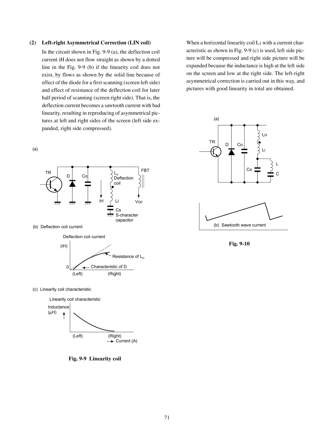
(2)Left-right Asymmetrical Correction (LIN coil)

In the circuit shown in Fig. 9-9 (a), the deflection coil current iH does not flow straight as shown by a dotted line in the Fig. 9-9 (b) if the linearity coil does not exist, by flows as shown by the solid line because of effect of the diode for a first scanning (screen left side) and effect of resistance of the deflection coil for later half period of scanning (screen right side). That is, the deflection current becomes a sawtooth current with bad linearity, resulting in reproducing of asymmetrical pic- tures at left and right sides of the screen (left side ex- panded, right side compressed).

(a)

TR


LH

FBT

Co


D

Deflection


coil


iH

Li

Vcc


Cs


S-character


capacitor


(b) Deflection coil current Deflection coil current

(iH)

Resistance of LH

0 Characteristic of D

(Left)(Right)

(c) Linearity coil characteristic

Linearity coil characteristic

Inductance (μH)

(Left)(Right) Current (A)

Fig. 9-9 Linearity coil

When a horizontal linearity coil L1 with a current char- acteristic as shown in Fig. 9-9 (c) is used, left side pic- ture will be compressed and right side picture will be expanded because the inductance is high at the left side on the screen and low at the right side. The left-right asymmetrical correction is carried out in this way, and pictures with good linearity in total are obtained.

(a)


LH

TR

D Co


LI


L


Cs


C

(b) Sawtooth wave current

Fig. 9-10

71

Page 71
Image 71
Toshiba TW40F80 manual Left-right Asymmetrical Correction LIN coil, Linearity coil