13-4. Understanding Self Diagnosis Indication
In case that phenomenon always arises. See Fig.
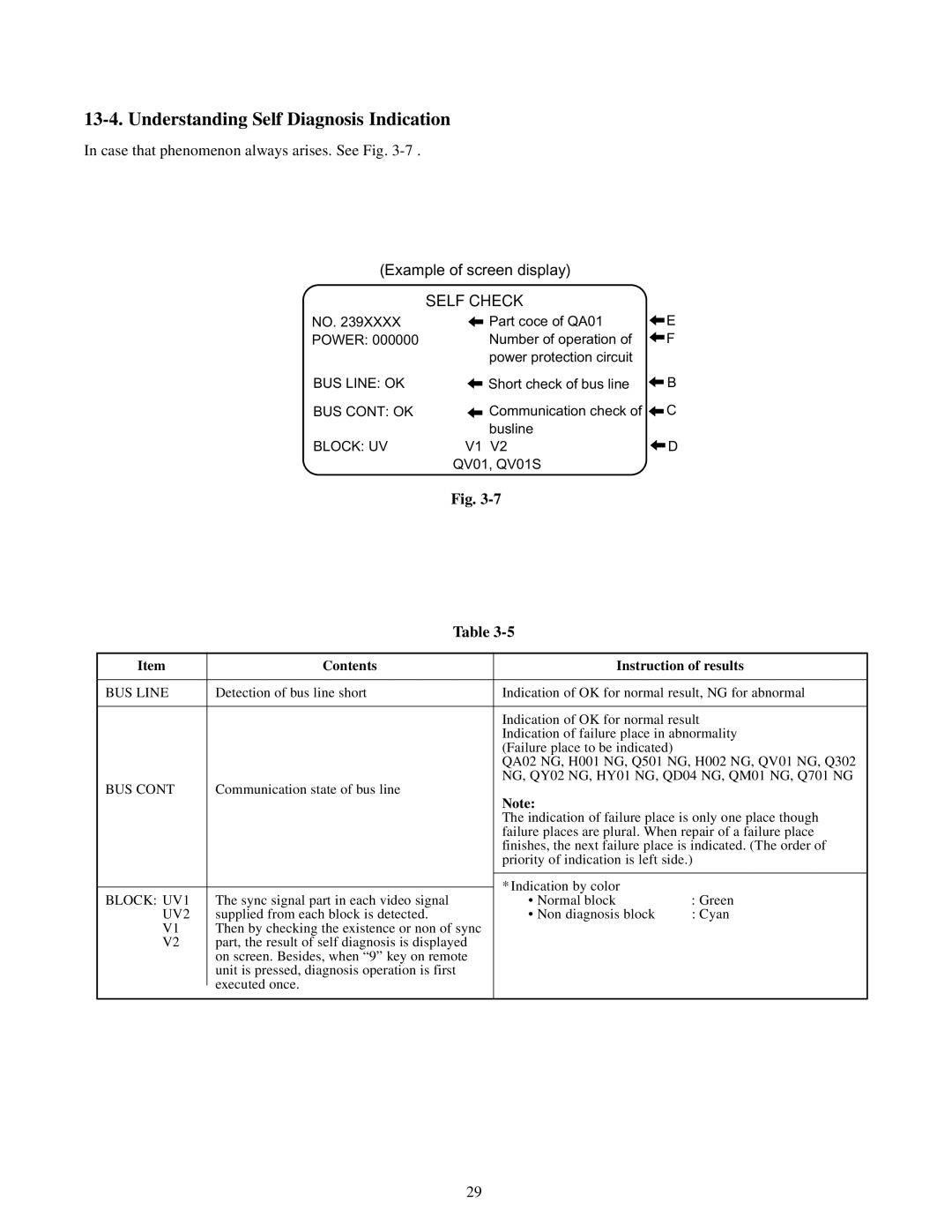
(Example of screen display)
SELF CHECK
NO. 239XXXX POWER: 000000
BUS LINE: OK
BUS CONT: OK
BLOCK: UV
Part coce of QA01 | E |
Number of operation of | F |
power protection circuit |
|
Short check of bus line | B |
Communication check of | C |
busline |
|
V1 V2 | D |
QV01, QV01S |
|
Fig.
| Table |
| |
|
|
| |
Item | Contents | Instruction of results | |
|
|
| |
BUS LINE | Detection of bus line short | Indication of OK for normal result, NG for abnormal | |
|
|
| |
|
| Indication of OK for normal result | |
|
| Indication of failure place in abnormality | |
|
| (Failure place to be indicated) |
|
|
| QA02 NG, H001 NG, Q501 NG, H002 NG, QV01 NG, Q302 | |
BUS CONT | Communication state of bus line | NG, QY02 NG, HY01 NG, QD04 NG, QM01 NG, Q701 NG | |
Note: |
| ||
|
|
| |
|
| The indication of failure place is only one place though | |
|
| failure places are plural. When repair of a failure place | |
|
| finishes, the next failure place is indicated. (The order of | |
|
| priority of indication is left side.) | |
|
|
|
|
|
| * Indication by color |
|
|
|
| |
BLOCK: UV1 | The sync signal part in each video signal | • Normal block | : Green |
UV2 | supplied from each block is detected. | • Non diagnosis block | : Cyan |
V1 | Then by checking the existence or non of sync |
|
|
V2 | part, the result of self diagnosis is displayed |
|
|
| on screen. Besides, when “9” key on remote |
|
|
| unit is pressed, diagnosis operation is first |
|
|
| executed once. |
|
|
|
|
| |
|
|
|
|
29