1-3. Audio Multiplex Demodulation Circuit
The sound multiplex composite signal
MVUS34S
Then, both are fed to the matrix circuit. At the same time, each of the stereo pilot signal fH and the SAP pilot signal 5fH is also demodulated to obtain an identification voltage. With the identification voltage thus obtained and the user control voltage are used to control the matrix.
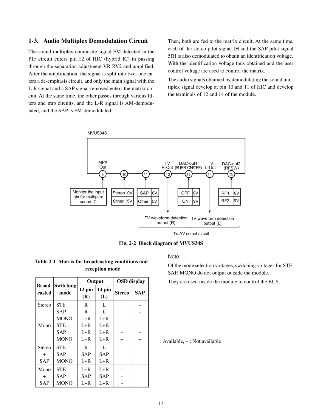
The audio signals obtained by demodulating the sound mul- tiplex signal develop at pin 10 and 11 of HIC and develop the terminals of 12 and 14 of the module.
MPX |
|
| TV | TV | ||
Out |
|
| (RFSW) | |||
9 | 10 | 11 | 12 | 13 | 14 | 15 |
Monitor the input pin for multiplex sound IC
Stereo 0V
Other 5V
|
|
|
SAP | 0V | |
|
|
|
Other | 5V | |
|
|
|
|
|
|
OFF | 0V | |
|
|
|
ON | 9V | |
|
|
|
|
|
|
RF1 | 0V | |
|
|
|
RF2 | 9V | |
|
|
|
TV waveform detection | TV waveform detection |
output (R) | output (L) |
To AV select circuit
Fig. 2-2 Block diagram of MVUS34S
Table 2-1 Matrix for broadcasting conditions and reception mode
Note:
Of the mode selection voltages, switching voltages for STE, SAP, MONO do not output outside the module.
Broad- | Switching | Output | OSD display | |||
|
|
|
| |||
12 pin | 14 pin |
|
| |||
casted | mode | Stereo | SAP | |||
|
| (R) | (L) |
|
| |
Stereo | STE | R | L | • | – | |
| SAP | R | L | – | ||
| • | |||||
|
|
|
|
| ||
Mono | MONO | L+R | L+R | • | – | |
STE | L+R | L+R | – | – | ||
| SAP | L+R | L+R | – | – | |
| MONO | L+R | L+R | – | – | |
|
|
|
|
|
| |
Stereo | STE | R | L | • | • | |
+ | SAP | SAP | SAP | |||
• | • | |||||
SAP | MONO | L+R | L+R | • | • | |
Mono | STE | L+R | L+R | – | • | |
+ | SAP | SAP | SAP | – | ||
• | ||||||
SAP | MONO | L+R | L+R | – | ||
• | ||||||
|
|
|
|
| ||
They are used inside the module to control the BUS.
•: Available,
13