8. LOCAL KEY DETECTION METHOD
17
18
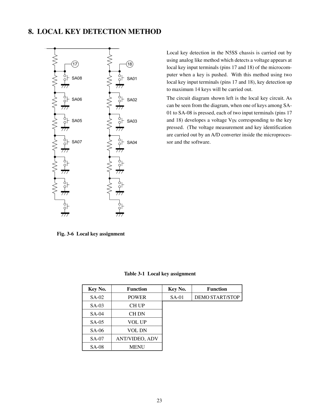
Local key detection in the N5SS chassis is carried out by
using analog like method which detects a voltage appears at
local key input terminals (pins 17 and 18) of the microcom-
puter when a key is pushed. With this method using two
SA08
SA01
local key input terminals (pins 17 and 18), key detection up to maximum 14 keys will be carried out.
SA06
SA05
SA07
SA02 | The circuit diagram shown left is the local key circuit. As |
| |
| can be seen from the diagram, when one of keys among SA- |
| 01 to |
SA03 | and 18) developes a voltage VIN corresponding to the key |
| pressed. (The voltage measurement and key identification |
| are carried out by an A/D converter inside the microproces- |
SA04 | sor and the software. |
Fig. 3-6 Local key assignment
Table
Key No. | Function | Key No. | Function |
|
|
|
|
POWER | DEMO START/STOP | ||
|
|
|
|
CH UP |
|
| |
|
|
|
|
CH DN |
|
| |
|
|
|
|
VOL UP |
|
| |
|
|
|
|
VOL DN |
|
| |
|
|
|
|
ANT/VIDEO, ADV |
|
| |
|
|
|
|
MENU |
|
|
23