efesotomasyon.com
E6581315
8. Commands and monitoring from the computer
Across the network, instructions (commands and frequency) can be sent to each inverter and the operating status of each inverter can be monitored.
8.1. Communication commands (commands from the computer)
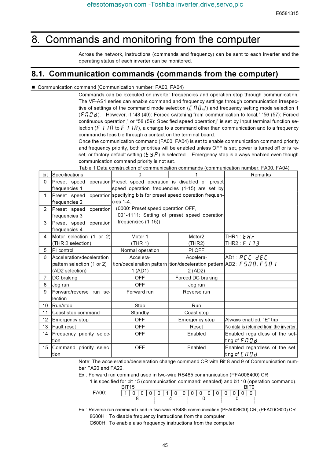
Communication command (Communication number: FA00, FA04)
Commands can be executed on inverter frequencies and operation stop through communication. The
Once the communication command (FA00, FA04) is set to enable communication command priority and frequency priority, both priorities will be enabled unless OFF is set, power is turned off or is re- set, or factory default setting () is selected. Emergency stop is always enabled even though communication command priority is not set.
Table 1 Data construction of communication commands (communication number: FA00, FA04)
bit | Specifications |
|
|
|
|
|
| 0 |
|
|
|
|
|
|
| 1 |
|
|
|
|
|
|
|
|
|
| Remarks |
| ||||||
0 | Preset | speed | operation | Preset |
| speed | operation |
| is | disabled | or | preset |
|
|
|
|
|
|
| |||||||||||||||
| frequencies 1 |
|
| speed | operation | frequencies | by |
|
|
|
|
|
|
| ||||||||||||||||||||
1 | Preset | speed | operation | specifying bits for preset speed operation frequen- |
|
|
|
|
|
|
| |||||||||||||||||||||||
| frequencies 2 |
|
| cies |
|
|
|
|
|
|
|
|
|
|
|
|
|
|
|
|
|
|
|
|
|
|
|
|
| |||||
2 | Preset | speed | operation | (0000: Preset speed operation OFF, |
|
|
|
|
|
|
|
|
|
|
|
|
| |||||||||||||||||
| frequencies 3 |
|
|
|
|
|
|
|
|
| ||||||||||||||||||||||||
3 | Preset | speed | operation | frequencies |
|
|
|
|
|
|
|
|
|
|
|
|
|
|
|
|
|
|
|
| ||||||||||
| frequencies 4 |
|
|
|
|
|
|
|
|
|
|
|
|
|
|
|
|
|
|
|
|
|
|
|
|
|
|
|
|
|
|
| ||
4 | Motor selection (1 or 2) |
|
|
| Motor 1 |
|
|
|
|
|
|
| Motor2 |
|
|
|
| THR1 : |
| |||||||||||||||
| (THR 2 selection) |
|
|
|
| (THR 1) |
|
|
|
|
|
|
| (THR2) |
|
|
|
| THR2 : |
| ||||||||||||||
5 | PI control |
|
|
| Normal operation |
|
|
|
|
| PI OFF |
|
|
|
|
|
|
|
|
|
|
| ||||||||||||
6 | Acceleration/deceleration |
|
| Accelera- |
|
|
|
|
|
| Accelera- |
|
|
|
| AD1 : , |
| |||||||||||||||||
| pattern selection (1 or 2) | tion/deceleration pattern | tion/deceleration pattern | AD2 : , |
| |||||||||||||||||||||||||||||
| (AD2 selection) |
|
|
|
|
| 1 (AD1) |
|
|
|
|
|
| 2 (AD2) |
|
|
|
|
|
|
|
|
|
|
| |||||||||
7 | DC braking |
|
|
|
|
|
| OFF |
|
|
|
|
| Forced DC braking |
|
|
|
|
|
|
| |||||||||||||
8 | Jog run |
|
|
|
|
|
|
| OFF |
|
|
|
|
|
|
|
| Jog run |
|
|
|
|
|
|
|
|
|
|
| |||||
9 | Forward/reverse | run se- |
| Forward run |
|
|
| Reverse run |
|
|
|
|
|
|
|
|
| |||||||||||||||||
| lection |
|
|
|
|
|
|
|
|
|
|
|
|
|
|
|
|
|
|
|
|
|
|
|
|
|
|
|
|
|
|
|
|
|
10 | Run/stop |
|
|
|
|
|
| Stop |
|
|
|
|
|
|
|
| Run |
|
|
|
|
|
|
|
|
|
|
| ||||||
11 | Coast stop command |
|
|
| Standby |
|
|
|
|
| Coast stop |
|
|
|
|
|
|
|
|
| ||||||||||||||
12 | Emergency stop |
|
|
|
|
| OFF |
|
|
|
|
| Emergency stop |
|
| Always enabled, “E” trip |
| |||||||||||||||||
13 | Fault reset |
|
|
|
|
|
| OFF |
|
|
|
|
|
|
|
| Reset |
|
|
|
| No data is returned from the inverter. |
| |||||||||||
14 | Frequency | priority | selec- |
|
|
| OFF |
|
|
|
|
|
|
| Enabled |
|
|
|
| Enabled regardless of the set- |
| |||||||||||||
| tion |
|
|
|
|
|
|
|
|
|
|
|
|
|
|
|
|
|
|
|
|
|
|
|
|
|
| ting of |
| |||||
15 | Command | priority | selec- |
|
|
| OFF |
|
|
|
|
|
|
| Enabled |
|
|
|
| Enabled regardless of the set- |
| |||||||||||||
| tion |
|
|
|
|
|
|
|
|
|
|
|
|
|
|
|
|
|
|
|
|
|
|
|
|
|
| ting of |
| |||||
|
|
| Note: The acceleration/deceleration change command OR with Bit 8 and 9 of Communication num- | |||||||||||||||||||||||||||||||
|
|
| ber FA20 and FA22. |
|
|
|
|
|
|
|
|
|
|
|
|
|
|
|
|
|
|
|
|
|
|
|
|
|
|
| ||||
|
|
| Ex.: Forward run command used in | |||||||||||||||||||||||||||||||
|
|
|
| 1 is specified for bit 15 (communication command: enabled) and bit 10 (operation command). | ||||||||||||||||||||||||||||||
|
|
|
| FA00: |
| BIT15 |
|
|
|
|
|
|
|
|
|
|
|
|
|
|
|
|
|
|
|
|
| BIT0 | ||||||
|
|
|
|
| 1 |
| 0 |
| 0 | 0 |
| 0 | 1 |
| 0 | 0 |
| 0 |
| 0 |
| 0 |
| 0 |
| 0 | 0 |
| 0 | 0 |
|
| ||
|
|
|
|
|
|
|
|
|
| 8 |
|
|
|
|
| 4 |
|
|
|
| 0 |
|
|
|
|
|
|
| 0 |
|
|
|
| |
Ex.: Reverse run command used in
C600H : To enable also frequency instructions from the computer
45