efesotomasyon.com
E6581315
6.2. Transmission format for inter-drive communication
Data type is handled in hexadecimal notation and the transmission characters are treated with the binary (HEX) code.
The transmission format is basically the same to the case of binary mode. S command is used and the slave inverters do not return the data.
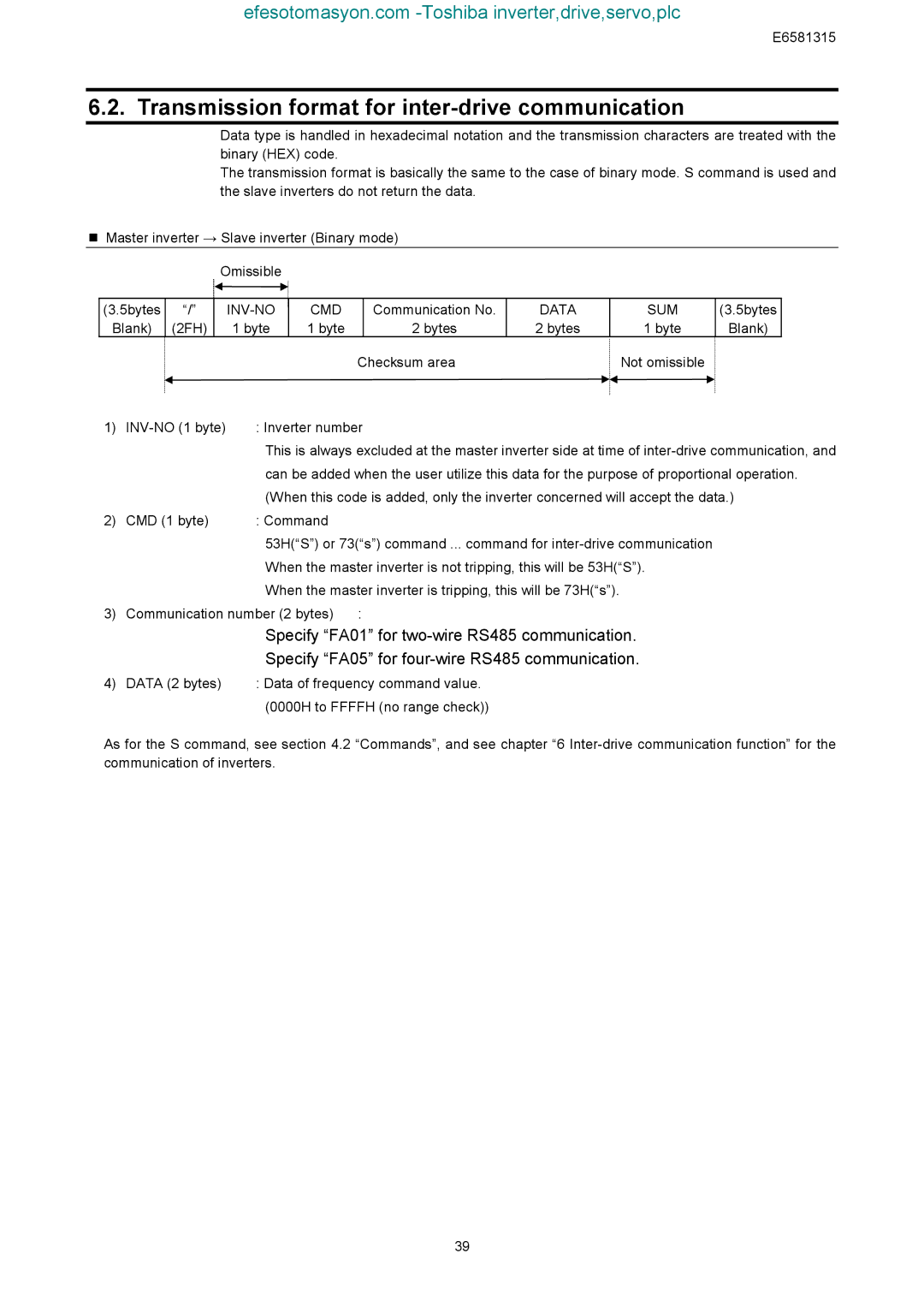
Master inverter → Slave inverter (Binary mode)
Omissible
(3.5bytes | “/” |
|
| CMD |
| Communication No. | DATA | SUM | (3.5bytes |
Blank) | (2FH) |
| 1 byte | 1 byte |
| 2 bytes | 2 bytes | 1 byte | Blank) |
|
|
|
|
| Checksum area |
| Not omissible |
| |
1) | : Inverter number |
|
|
| |||||
|
| This is always excluded at the master inverter side at time of |
|
| can be added when the user utilize this data for the purpose of proportional operation. |
|
| (When this code is added, only the inverter concerned will accept the data.) |
2) | CMD (1 byte) | : Command |
|
| 53H(“S”) or 73(“s”) command ... command for |
|
| When the master inverter is not tripping, this will be 53H(“S”). |
|
| When the master inverter is tripping, this will be 73H(“s”). |
3) | Communication number (2 bytes) : | |
|
| Specify “FA01” for |
|
| Specify “FA05” for |
4) | DATA (2 bytes) | : Data of frequency command value. |
|
| (0000H to FFFFH (no range check)) |
As for the S command, see section 4.2 “Commands”, and see chapter “6
39