E6581315②
Tosvert VF-AS1 Series RS485 Communication Function
E6581315
Read first Safety precautions
Contents
BIT15 BIT8BIT7 BIT0
General outlines of the communication function
Bit Word
BIT2
Data transmission specifications
About the handling of received frames
Communication protocol
MOUBUS-RTU
Toshiba Inverter Protocol
Binary mode 2FH
Data transmission format
Data transmission format used in Ascii mode
INV-NO CMD
Data
28H Bytes Checksum area
5bytes Blank
Data SUM
INV-NO
Data transmission format used in binary mode
Returned for the 57H W and 50H P commands
Command received
Byte Bytes
Sum 1 bytes Checksum not omissible 00H to FFH
2FH Byte 4EH6EH Bytes
Norn
Transmission format of Block Communication
Page
Bytes Blank Start Code
INV-NO
Dummy data is required for this command
Commands
Reads the data with the specified communication number
Block communication Computer Inverter
RFE03077BCR
RFE03CR
Page
Format error Data transmission format does not match
Transmission errors
Communication There is no communication number that matches
Broadcast communication function
VF-AS1
Ascii mode Computer → Inverter Inverter → Computer
Examples of the use of communication commands
From the computer H = 24d trip status
RFC90CR
Examples of Communication programs
Next
=LENS$ For I=1 to L
Input #1,B$
Goto
If Count 0 then T=TIMER
160 T=TIMER COUNT=TIMER-T
Print #1,B$
Page
MSComm1.Output = Text2.Text & Chr13 End Sub
End If
Text2.Text = Text1.Text = End Sub
Inverter number
MODBUS-RTU protocol
MODBUS-RTU transmission format
Read command
CRC
Blank Command 1 byte
Write command
5bytes Blank Command 1 byte
Text size is 8 bytes fixed Inverter
CRC Generation
Error codes
Bit counter =
End Return CRC
Inter-drive communication
Never use pin-7 P11 QWiring 4-wire RS485 communication)
E6581315 QWiring 2-wire RS485 communication
Page
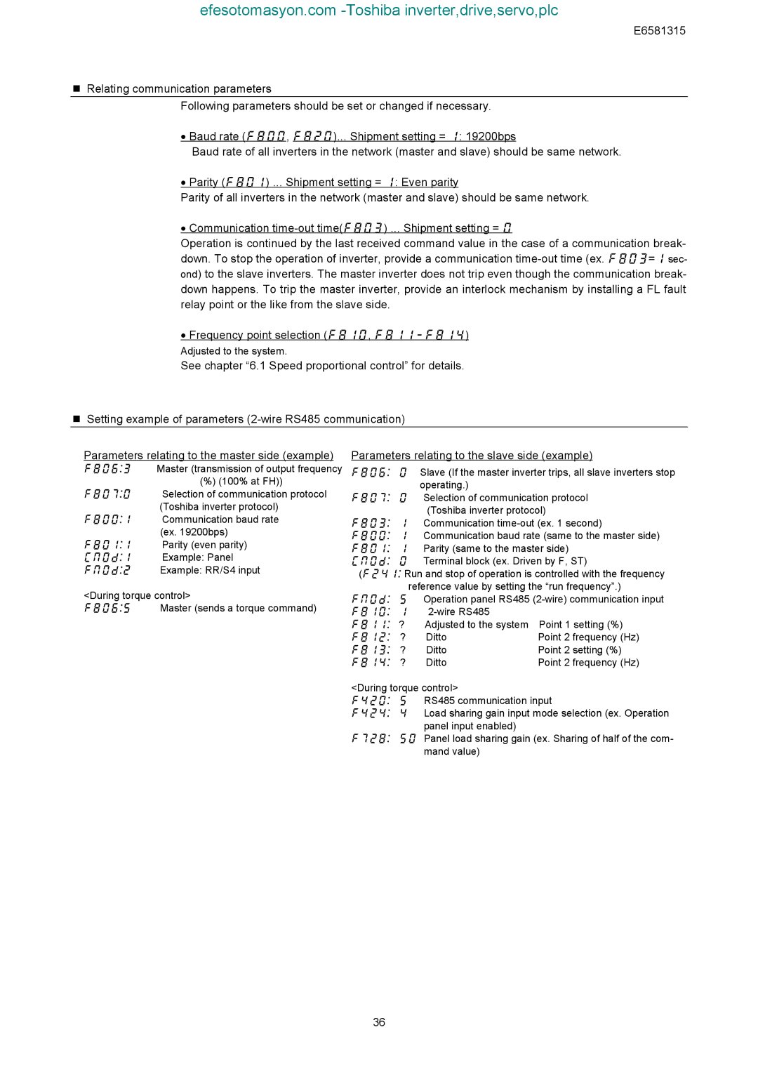
Parameters relating to the slave side example
=0.01%
Proportional control of speed
90.00Hz 45.00Hz
Slave 100.00Hz 00%
Slave 100.00Hz1 00%
80.00Hz 40.00Hz
INV-NO 1 byte Inverter number
Transmission format for inter-drive communication
0OFF
Communication parameters
MODBUS-RTU
Inverter number
Baud rate, , Parity
PC → INV
„ Timer Time-out period Computer link
Master INV To Slave
INV INV → PC PC → INV
Free notes
Send waiting time ,
Use this function for the following case
Communication commands commands from the computer
Commands and monitoring from the computer
PI OFF
OFF
Forcibly braked Preliminary excitation
Electric Power quantity
Brake release B
Braking answer BA
Wire RS485 communication FA32
„ FM analog output FA51
„ Terminal board output data FA50
„ AM analog output FA52
Output terminal no Specified data output
RFD00CR
Monitoring from the computer
Unit 0.01% N·m
RES
„ Input terminal board status FD06, FE06
Input terminal function selection 9 f119
BIT15
„ Output terminal board status FD07, FE07
ST=ON ST=OFF
„ Inverter operating status 1 FD01, FE01
„ Inverter operating status 3 FD49, FE49
„ Inverter operating status 2 FD42, FE42
„ Inverter operating frequency mode status FD46, FE46
„ Inverter operating command mode status FD45, FE45
Preset speed operation
„ Cumulative operation time alarm monitor FE79
„ Alarm information monitor FC91
Bit Specifications Remarks
E6581315
Model Data
„ Inverter model capacity code FB05
Parameter Name Range Setting
LED setting by communication
Utilizing panel LEDs and keys by communication
„ Block Communication Function for LED Display
Blank
Ascii LED display data code 00H-1FH are blank
FA10=0
Key utilization by communication
FA10=1
Parameter data
ROM
EEP
Page
FE02 Frequency command value 01Hz
Alarm code
FE19 Torque command
FE29 Input power
E6581315 FD50 Light-load high-speed torque 01%
Tion FE80 Cumulative power on time
FE84 Binary input value option
Can
Appendix 1 Table of data codes
SUB
ESC
Response time „ Data transmission time
Appendix 2 Response time
VF-A7
Appendix 3 Compatibility with the communication function
Appendix 4 Troubleshooting
Appendix 5 Connecting for RS485 communication
RXB
RXA
TXA
TXB