efesotomasyon.com
E6581315
6.1. Proportional control of speed
Proportional control of frequency can be performed in two ways: control by selecting frequency points and control by adjusting the ratio to the maximum frequency. This section explains propor- tional control of inverters by means of a master inverter
Proportional control can also be performed in units of Hz using ordinary write commands (W and P commands) (frequency point selection only). For proportional control in units of %, however, the S command should be used.
*For proportional control by selecting frequency points, the gradient can be set variously according to the way each inverter is used. For proportional control by controlling the ratio to the maximum frequency, settings can be made easily without consideration of the rate at which the frequency is increased or decreased to the target frequency.
•Data sent by the master inverter to slave inverters in
fc(%)= | Master side fc×10000 | (1=0.01%) | |
Master side FH | |||
|
|
*Fractions under 1 (0.01%) are omitted. Therefore, an error of 0.01% is introduced at the maxi- mum.
•Conversion of the frequency command received by a slave inverter (when the “frequency point selection” option is not selected)
The value obtained by the following conversion calculation is written in RAM as a frequency com- mand value.
fc( Hz ) = | Slave receive data(%)⋅ Slave side FH | (1=0.01Hz) | |
10000 | |||
|
|
*Fractions under 1 (0.01Hz) are omitted. Therefore, an error of 0.01Hz is introduced at the maxi- mum.
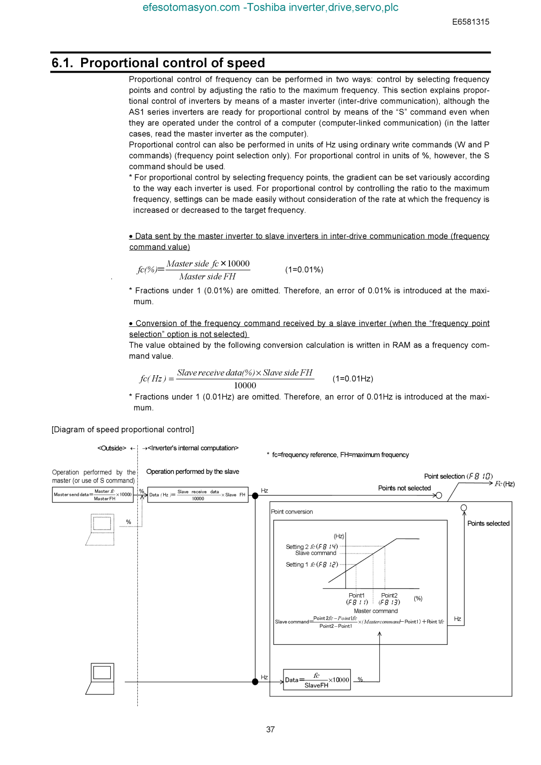
[Diagram of speed proportional control]
<Outside> ← →<Inverter's internal computation>
Operation performed | by the | Operation performed by the slave | ||||||
master (or use of S command) |
|
|
|
| ||||
|
|
|
|
|
|
|
|
|
Master send data= | Master fc |
| ⋅ 10000 |
| % | Data ( Hz )= | Slave receive data | ⋅ Slave FH |
Master FH |
| 10000 | ||||||
|
|
|
|
|
| |||
|
|
|
|
|
|
|
|
|
%
* fc=frequency reference, FH=maximum frequency |
| ||
| Point selection () | Fc (Hz) | |
Hz | Points not selected | ||
| |||
Point conversion |
|
|
|
|
| |
|
|
|
|
|
| Points selected |
| (Hz) |
|
|
|
|
|
| Setting 2 fc () |
|
|
|
|
|
| Slave command |
|
|
|
|
|
| Setting 1 fc () |
|
|
|
|
|
| Point1 | Point2 | (%) |
| ||
| () | () |
| |||
|
|
| ||||
|
| Master command |
|
| ||
| Point 2fc − Point1fc | ⋅( Mastercommand-Point1)+Point1fc | Hz | |||
| Slave command= Point2− Point1 |
|
| |||
Hz | fc |
|
|
|
|
|
Data=SlaveFH⋅10000 |
| % |
|
|
| |
|
|
|
|
| ||
37 |
|
|
|
|
|
|