efesotomasyon.com
E6581315
Output terminal board status (FD07, FE07)
Output terminal board status (current status): “Communication Number FD07”
Output terminal board status (status immediately before the occurrence of a trip): “Communication Number FE07”
Using terminal function selection parameters, functions can be assigned individually to the termi- nals on the output terminal board.
When using a terminal as a monitoring terminal, check beforehand the function assigned to each terminal.
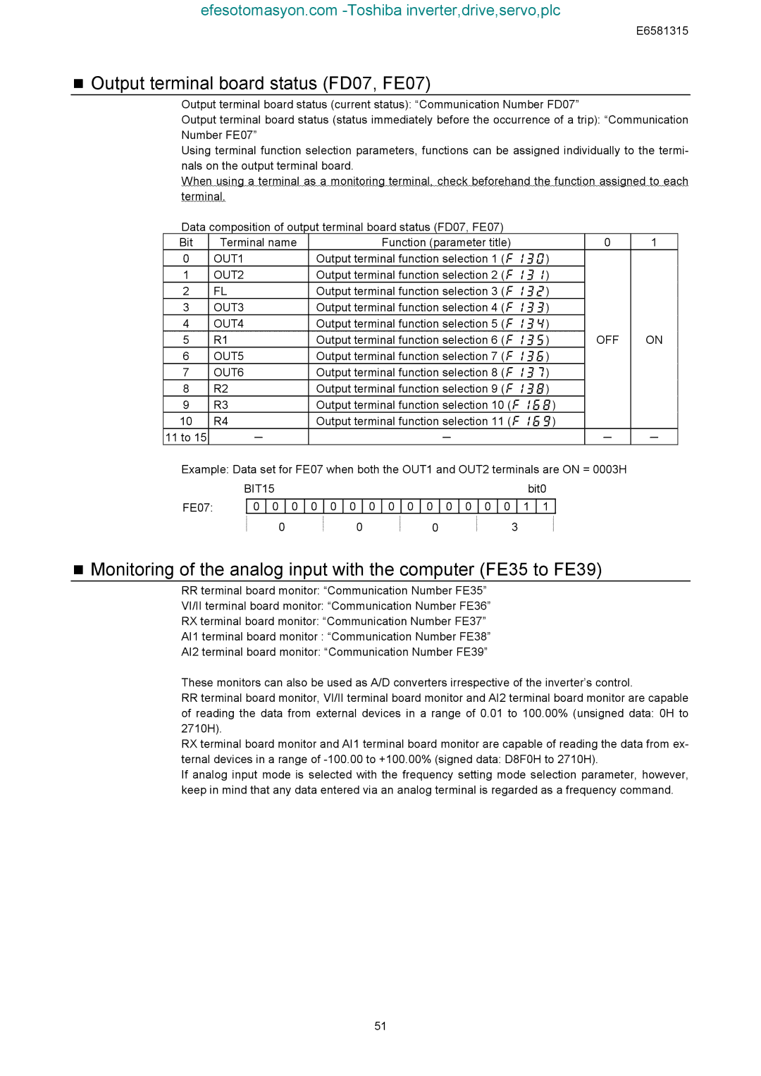
Data composition of output terminal board status (FD07, FE07)
Bit |
| Terminal name |
|
|
|
|
| Function (parameter title) |
|
|
|
| 0 | 1 | ||||||||||
0 |
| OUT1 |
|
|
| Output terminal function selection 1 (f130) |
|
| ||||||||||||||||
1 |
| OUT2 |
|
|
| Output terminal function selection 2 (f131) |
|
| ||||||||||||||||
2 |
| FL |
|
|
| Output terminal function selection 3 (f132) |
|
| ||||||||||||||||
3 |
| OUT3 |
|
|
| Output terminal function selection 4 (f133) |
|
| ||||||||||||||||
4 |
| OUT4 |
|
|
| Output terminal function selection 5 (f134) |
|
| ||||||||||||||||
5 |
| R1 |
|
|
| Output terminal function selection 6 (f135) | OFF | ON | ||||||||||||||||
6 |
| OUT5 |
|
|
| Output terminal function selection 7 (f136) |
|
| ||||||||||||||||
7 |
| OUT6 |
|
|
| Output terminal function selection 8 (f137) |
|
| ||||||||||||||||
8 |
| R2 |
|
|
| Output terminal function selection 9 (f138) |
|
| ||||||||||||||||
9 |
| R3 |
|
|
| Output terminal function selection 10 (f168) |
|
| ||||||||||||||||
10 |
| R4 |
|
|
| Output terminal function selection 11 (f169) |
|
| ||||||||||||||||
11 to 15 |
|
| - |
|
|
|
|
|
|
|
|
|
|
| - |
|
|
|
|
|
|
| - | - |
Example: Data set for FE07 when both the OUT1 and OUT2 terminals are ON = 0003H |
| |||||||||||||||||||||||
|
| BIT15 |
|
|
|
|
|
|
|
|
|
|
|
|
|
|
| bit0 |
|
| ||||
|
|
|
|
|
|
|
|
|
|
|
|
|
|
|
|
|
|
|
|
|
|
|
| |
FE07: |
| 0 | 0 | 0 |
| 0 | 0 | 0 |
| 0 | 0 | 0 | 0 | 0 | 0 | 0 | 0 |
| 1 | 1 |
|
|
| |
|
|
|
| 0 |
|
|
|
|
| 0 |
|
|
| 0 |
|
|
|
| 3 |
|
|
|
| |
Monitoring of the analog input with the computer (FE35 to FE39)
RRterminal board monitor: “Communication Number FE35” VI/II terminal board monitor: “Communication Number FE36” RX terminal board monitor: “Communication Number FE37” AI1 terminal board monitor : “Communication Number FE38” AI2 terminal board monitor: “Communication Number FE39”
These monitors can also be used as A/D converters irrespective of the inverter’s control.
RRterminal board monitor, VI/II terminal board monitor and AI2 terminal board monitor are capable of reading the data from external devices in a range of 0.01 to 100.00% (unsigned data: 0H to 2710H).
RX terminal board monitor and AI1 terminal board monitor are capable of reading the data from ex- ternal devices in a range of
If analog input mode is selected with the frequency setting mode selection parameter, however, keep in mind that any data entered via an analog terminal is regarded as a frequency command.
51