Installation and Wiring
Wiring
!WARNING
Warning! Disconnect all elec- trical power before servicing unit to prevent injury or death due to electrical shock. Use copper conductors only. The use of aluminum or other incorrect types of wire may result in overheating and equipment damage.
!CAUTION
Caution: To prevent damage to the unit ventilator, refer to the diagram provided on the inside of the unit's access panel for specific wiring infor-
mation. All controls are wired at the factory. Single point power, zone sensor, and communication wiring is to be installed by the contractor.
Important! All wiring must comply with state, local, and federal guidelines. Contact the appropriate local agency for furthur information.
Important! Wires for temperature sensors, communication lines, 24 VAC, and contact closure sensing inputs should not be bundled with or run near high voltage wiring.
qPower wiring must be separated from the Tracer ZN.520 and all low voltage wires. External input wires should be run in separate conduits from high voltage wires.
qWires connected to pin headers should be formed and routed so as to cause minimum strain on the Tracer ZN.520 connector.
qA minimum of 1.5" clearance (from the pin centerline) for wires up to 16 AWG is recommended for bending and forming wires.
qAll sensor and input circuits are at or near ground potential. Do not connect any sensor or input circuit to an external ground connection.
qA
qTable 7: Tracer ZN.520 Wiring Requirements, shows Tracer ZN.520 wire types and lengths.
Table 7: Tracer ZN.520 Wiring Requirements
Application | Wire Type | Length | |
|
|
| |
Contact Closure | 18 AWG | Up to | |
1000 ft. | |||
|
| ||
24 VAC | Up to | ||
1000 ft. | |||
|
| ||
Thermostat | Up to | ||
1000 ft. | |||
|
| ||
Zone | Up to | ||
Sensor | 200 ft. | ||
| |||
Communications | Belden 8760 | Up to | |
| or equivalent | 5000 ft. |
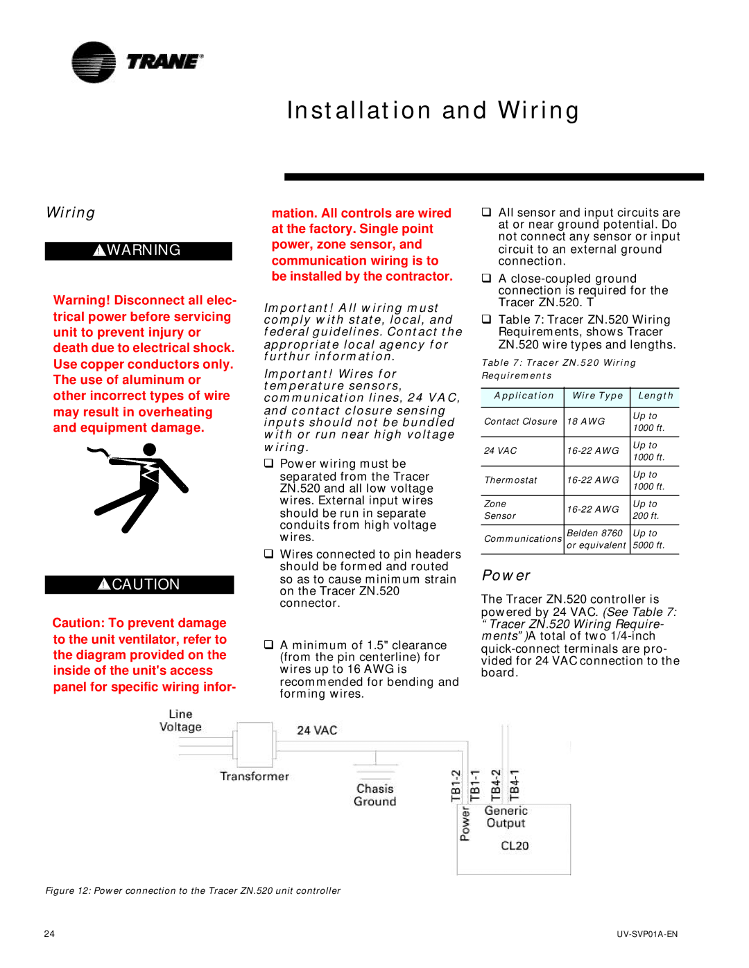
Power
The Tracer ZN.520 controller is
powered by 24 VAC. (See Table 7: “Tracer ZN.520 Wiring Require- ments”)A total of two
Figure 12: Power connection to the Tracer ZN.520 unit controller
24 |