Unit Operation
4 = Night Purge (air changeover) not supported
5=
6= Off (no unit operation allowed)
7= Test (special test mode)
8= Emergency Heat not supported
9 = Fan Only (no heating or cooling allowed)
All other enumerations will be in- terpreted as Auto.
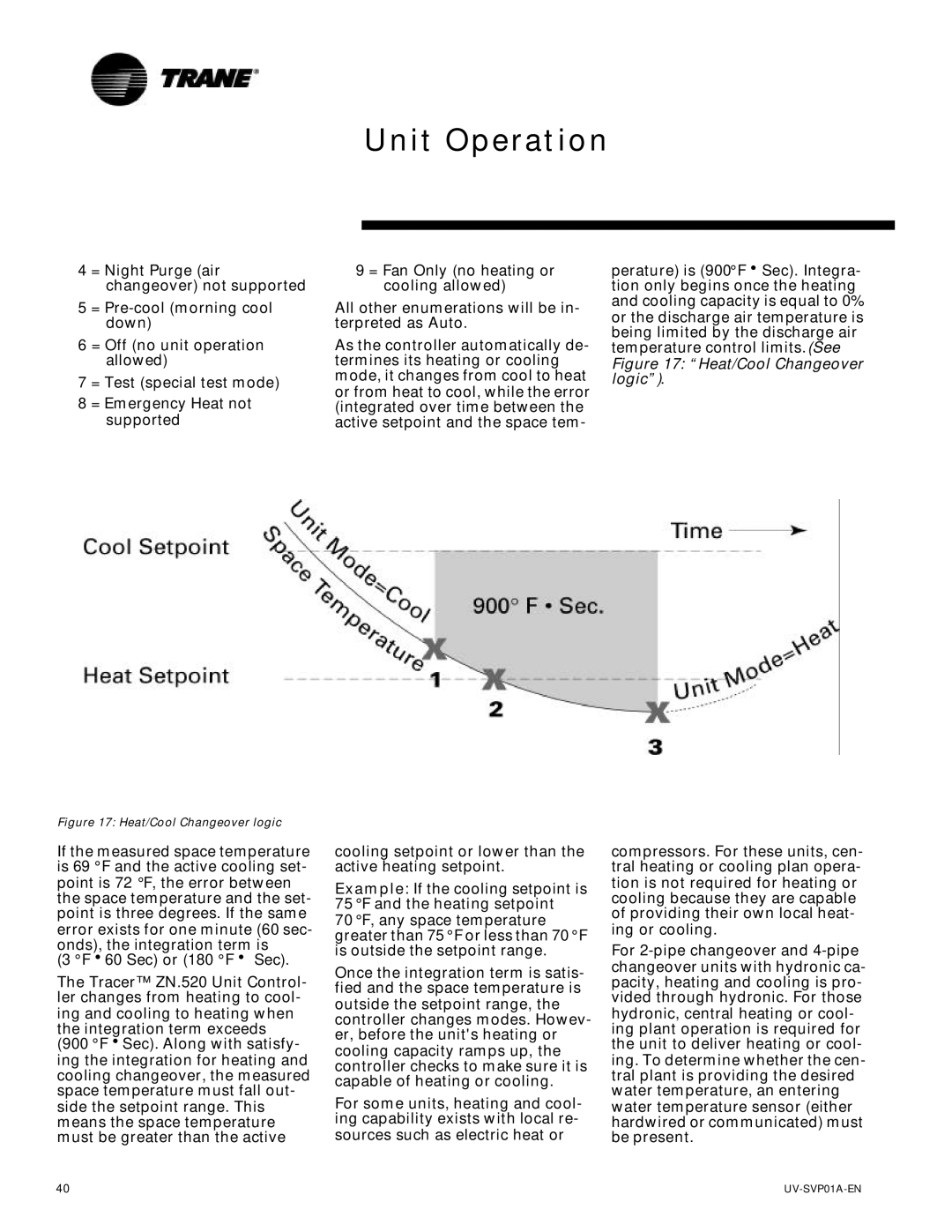
As the controller automatically de- termines its heating or cooling mode, it changes from cool to heat or from heat to cool, while the error (integrated over time between the active setpoint and the space tem-
perature) is (900°FhSec). Integra- tion only begins once the heating and cooling capacity is equal to 0% or the discharge air temperature is being limited by the discharge air temperature control limits.(See
Figure 17: “Heat/Cool Changeover logic”).
Figure 17: Heat/Cool Changeover logic
If the measured space temperature is 69 °F and the active cooling set- point is 72 °F, the error between the space temperature and the set- point is three degrees. If the same error exists for one minute (60 sec- onds), the integration term is
(3 °Fh60 Sec) or (180 °Fh Sec).
The Tracer™ ZN.520 Unit Control- ler changes from heating to cool- ing and cooling to heating when the integration term exceeds
(900 °FhSec). Along with satisfy- ing the integration for heating and cooling changeover, the measured space temperature must fall out- side the setpoint range. This means the space temperature must be greater than the active
cooling setpoint or lower than the active heating setpoint.
Example: If the cooling setpoint is 75 °F and the heating setpoint
70 °F, any space temperature greater than 75 °F or less than 70 °F is outside the setpoint range.
Once the integration term is satis- fied and the space temperature is outside the setpoint range, the controller changes modes. Howev- er, before the unit's heating or cooling capacity ramps up, the controller checks to make sure it is capable of heating or cooling.
For some units, heating and cool- ing capability exists with local re- sources such as electric heat or
compressors. For these units, cen- tral heating or cooling plan opera- tion is not required for heating or cooling because they are capable of providing their own local heat- ing or cooling.
For
40 |