Controller Features
Each Tracer ZN.520 unit controller circuit board is equipped with en- hancements to help facilitate ser- vice, testing, and diagnosis.
Each board has
qManual test button,
qStatus LED,
qCommunication status LED,
qService button,
qQuick terminal connectors, and
qEasy to read screen printing. (See Figure 1: “Tracer ZN.520 Control Board”).
Service
The Trane Tracer ZN.520 unit con- troller is serviced using Rover®, the ICS software service too. Rover is designed to support the Tracer ZN.520 unit controller on the class- room unit ventilator.
For “remote” access to the com- municating units, the zone sensors offered with the Tracer ZN.520 have a telephone style
3:“Rover service tool connected to the
The zone sensor may also be used when trying to locate a unit. By pressing the ON button on the zone sensor for 5 seconds or using the “wink” command in Rover, the cir- cuit board receives the signal caus- ing the Communication LED to “wink”. Winking allows visual identifier on the board for service technicians.
The Tracer ZN.520 also includes features such as a test output to manually test all of the end devices and color coded wires (i.e. red for heating valves and blue for cooling valves) to aid in the troubleshoot- ing process.(See “Manual Output
Test” on page 48, for more infor- mation.)
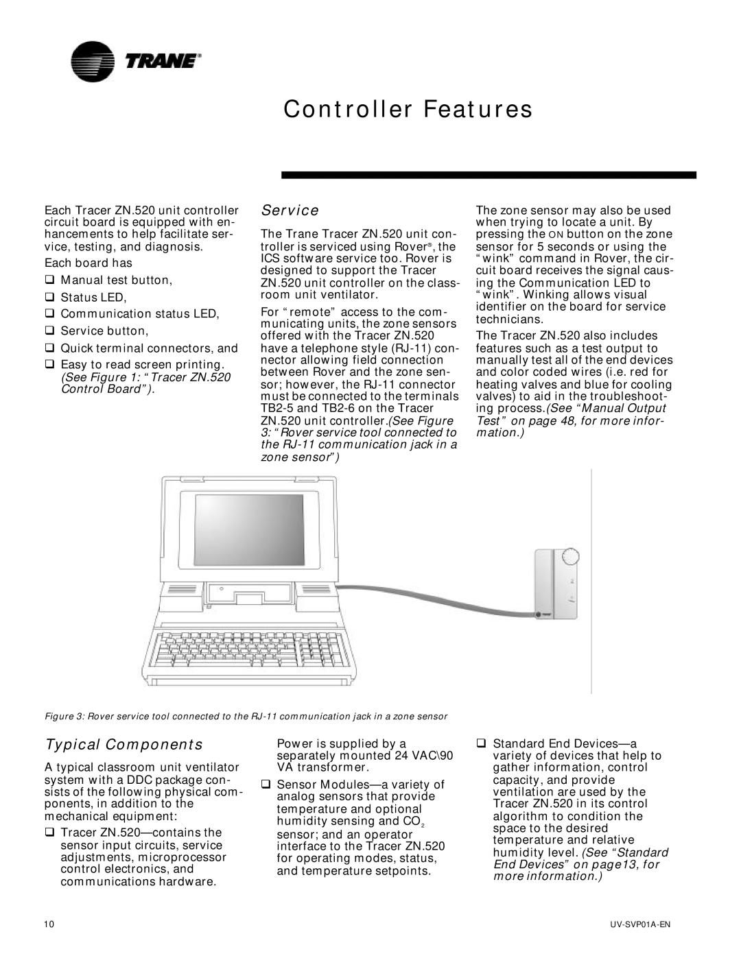
Figure 3: Rover service tool connected to the RJ-11 communication jack in a zone sensor
Typical Components
A typical classroom unit ventilator system with a DDC package con- sists of the following physical com- ponents, in addition to the mechanical equipment:
qTracer
Power is supplied by a separately mounted 24 VAC\90 VA transformer.
qSensor
qStandard End
10 |