Unit Operation
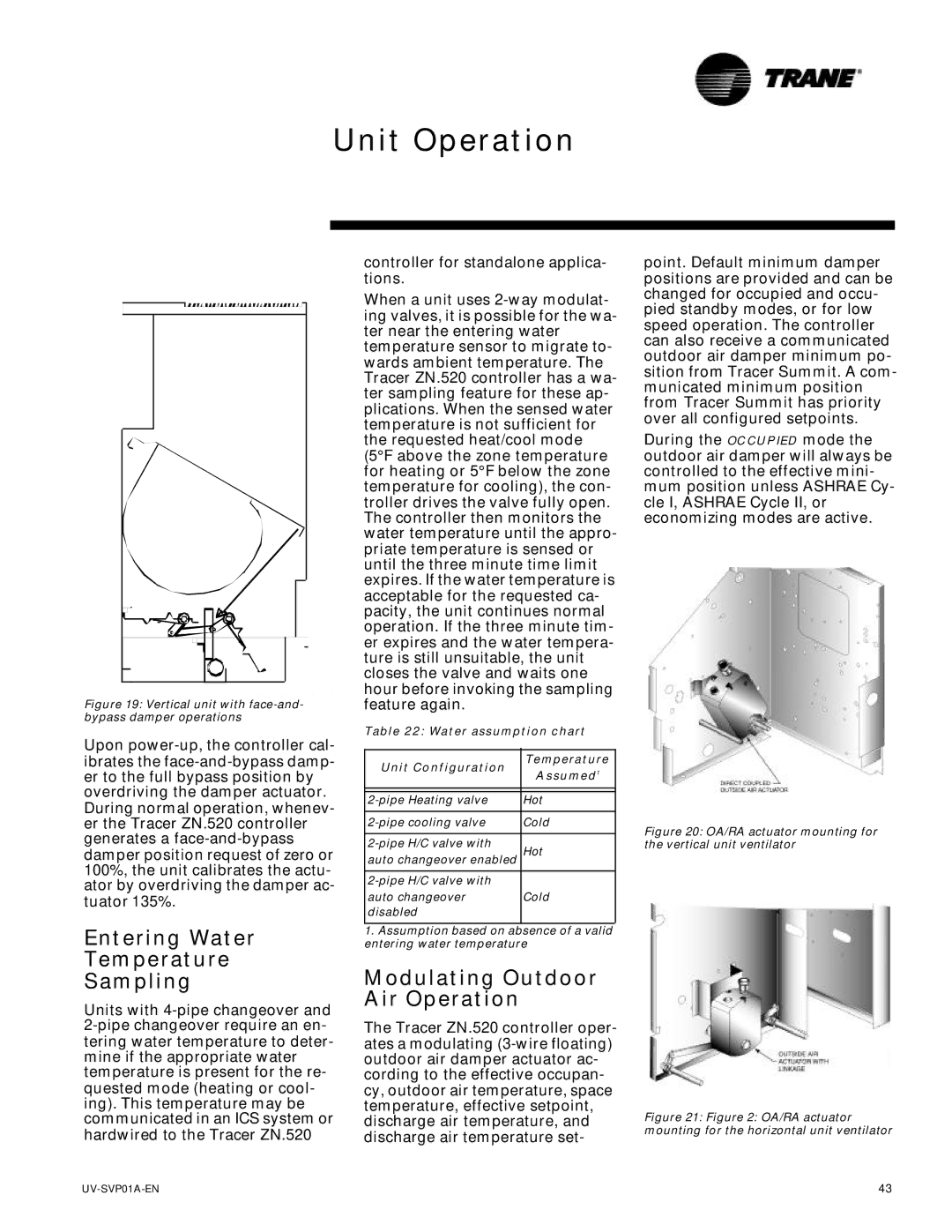
Figure 19: Vertical unit with face-and- bypass damper operations
Upon power-up, the controller cal-
controller for standalone applica- tions.
When a unit uses 2-way modulat- ing valves, it is possible for the wa- ter near the entering water temperature sensor to migrate to- wards ambient temperature. The Tracer ZN.520 controller has a wa- ter sampling feature for these ap- plications. When the sensed water temperature is not sufficient for the requested heat/cool mode (5°F above the zone temperature for heating or 5°F below the zone temperature for cooling), the con- troller drives the valve fully open. The controller then monitors the water temperature until the appro- priate temperature is sensed or until the three minute time limit expires. If the water temperature is acceptable for the requested ca- pacity, the unit continues normal operation. If the three minute tim- er expires and the water tempera- ture is still unsuitable, the unit closes the valve and waits one hour before invoking the sampling feature again.
Table 22: Water assumption chart
point. Default minimum damper positions are provided and can be changed for occupied and occu- pied standby modes, or for low speed operation. The controller can also receive a communicated outdoor air damper minimum po- sition from Tracer Summit. A com- municated minimum position from Tracer Summit has priority over all configured setpoints.
During the OCCUPIED mode the outdoor air damper will always be controlled to the effective mini- mum position unless ASHRAE Cy- cle I, ASHRAE Cycle II, or economizing modes are active.
ibrates the face-and-bypass damp- er to the full bypass position by overdriving the damper actuator. During normal operation, whenev- er the Tracer ZN.520 controller generates a face-and-bypass damper position request of zero or 100%, the unit calibrates the actu- ator by overdriving the damper ac- tuator 135%.
Unit Configuration
2-pipe Heating valve
2-pipe cooling valve
2-pipe H/C valve with auto changeover enabled
2-pipe H/C valve with auto changeover disabled
Temperature Assumed1
Hot
Cold
Hot
Cold
Figure 20: OA/RA actuator mounting for the vertical unit ventilator
Entering Water
Temperature
Sampling
Units with 4-pipe changeover and 2-pipe changeover require an en- tering water temperature to deter- mine if the appropriate water temperature is present for the re- quested mode (heating or cool- ing). This temperature may be communicated in an ICS system or hardwired to the Tracer ZN.520
1.Assumption based on absence of a valid entering water temperature
Modulating Outdoor Air Operation
The Tracer ZN.520 controller oper- ates a modulating (3-wire floating) outdoor air damper actuator ac- cording to the effective occupan- cy, outdoor air temperature, space temperature, effective setpoint, discharge air temperature, and discharge air temperature set-
Figure 21: Figure 2: OA/RA actuator mounting for the horizontal unit ventilator

