Troubleshooting
If a
page 54.for more information.)
Test Procedure
The procedure for testing is:
1.Press and hold the Test button for at least two seconds, then
release the button to start the test mode.
2.When manual output test mode begins, the controller turns off all outputs and cali- brates modulating end devices closed.
3.Press the Test button once to advance through the test sequence.
Note: To help ensure accurate testing do not press the test button more than once per second.
Alternatively, the manual output test can be controlled over the communications network by using Rover.
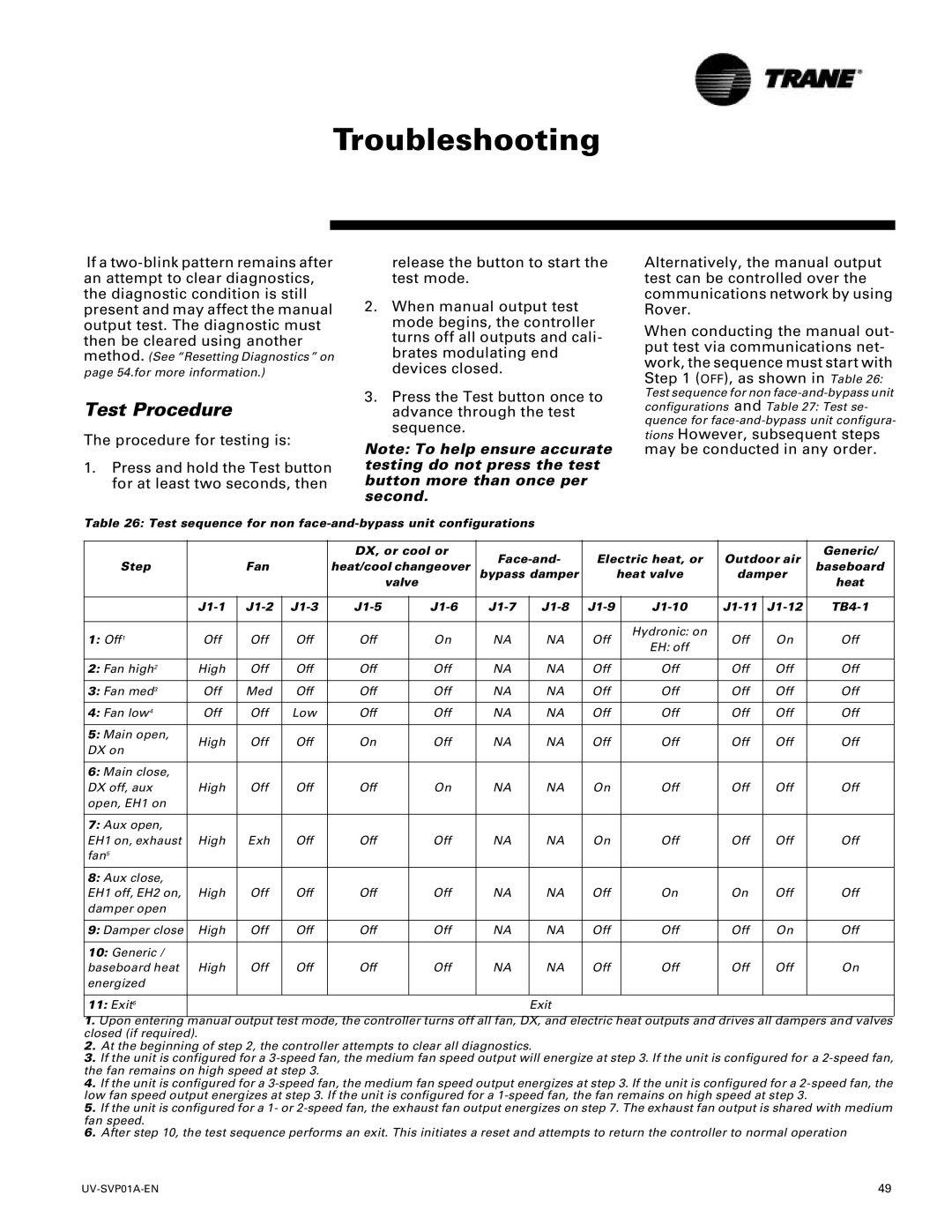
When conducting the manual out- put test via communications net- work, the sequence must start with Step 1 (OFF), as shown in Table 26: Test sequence for non
tions However, subsequent steps may be conducted in any order.
Table 26: Test sequence for non
|
|
|
| DX, or cool or | Electric heat, or | Outdoor air | Generic/ | |||||||
Step |
| Fan |
| heat/cool changeover | baseboard | |||||||||
|
| bypass damper |
| heat valve | damper | |||||||||
|
|
|
|
| valve |
| heat | |||||||
|
|
|
|
|
|
|
|
|
|
|
| |||
|
|
|
|
|
|
|
|
|
|
|
|
|
|
|
|
|
| ||||||||||||
|
|
|
|
|
|
|
|
|
|
|
|
|
|
|
1: Off1 | Off | Off | Off | Off |
| On | NA | NA | Off |
| Hydronic: on | Off | On | Off |
|
| EH: off | ||||||||||||
|
|
|
|
|
|
|
|
|
|
|
|
|
| |
|
|
|
|
|
|
|
|
|
|
|
|
|
|
|
2: Fan high2 | High | Off | Off | Off |
| Off | NA | NA | Off |
| Off | Off | Off | Off |
|
|
|
|
|
|
|
|
|
|
|
|
|
|
|
3: Fan med3 | Off | Med | Off | Off |
| Off | NA | NA | Off |
| Off | Off | Off | Off |
|
|
|
|
|
|
|
|
|
|
|
|
|
|
|
4: Fan low4 | Off | Off | Low | Off |
| Off | NA | NA | Off |
| Off | Off | Off | Off |
|
|
|
|
|
|
|
|
|
|
|
|
|
|
|
5: Main open, | High | Off | Off | On |
| Off | NA | NA | Off |
| Off | Off | Off | Off |
DX on |
|
| ||||||||||||
|
|
|
|
|
|
|
|
|
|
|
|
|
| |
|
|
|
|
|
|
|
|
|
|
|
|
|
|
|
6: Main close, |
|
|
|
|
|
|
|
|
|
|
|
|
|
|
DX off, aux | High | Off | Off | Off |
| On | NA | NA | On |
| Off | Off | Off | Off |
open, EH1 on |
|
|
|
|
|
|
|
|
|
|
|
|
|
|
|
|
|
|
|
|
|
|
|
|
|
|
|
|
|
7: Aux open, |
|
|
|
|
|
|
|
|
|
|
|
|
|
|
EH1 on, exhaust | High | Exh | Off | Off |
| Off | NA | NA | On |
| Off | Off | Off | Off |
fan5 |
|
|
|
|
|
|
|
|
|
|
|
|
|
|
|
|
|
|
|
|
|
|
|
|
|
|
|
|
|
8: Aux close, |
|
|
|
|
|
|
|
|
|
|
|
|
|
|
EH1 off, EH2 on, | High | Off | Off | Off |
| Off | NA | NA | Off |
| On | On | Off | Off |
damper open |
|
|
|
|
|
|
|
|
|
|
|
|
|
|
|
|
|
|
|
|
|
|
|
|
|
|
|
|
|
9: Damper close | High | Off | Off | Off |
| Off | NA | NA | Off |
| Off | Off | On | Off |
|
|
|
|
|
|
|
|
|
|
|
|
|
|
|
10: Generic / |
|
|
|
|
|
|
|
|
|
|
|
|
|
|
baseboard heat | High | Off | Off | Off |
| Off | NA | NA | Off |
| Off | Off | Off | On |
energized |
|
|
|
|
|
|
|
|
|
|
|
|
|
|
|
|
|
|
|
|
|
|
|
|
|
|
|
|
|
11: Exit6 |
|
|
|
|
|
|
| Exit |
|
|
|
|
|
|
|
|
|
|
|
|
|
|
|
|
|
|
|
|
|
1.Upon entering manual output test mode, the controller turns off all fan, DX, and electric heat outputs and drives all dampers and valves closed (if required).
2.At the beginning of step 2, the controller attempts to clear all diagnostics.
3.If the unit is configured for a
4.If the unit is configured for a
5.If the unit is configured for a 1- or
6.After step 10, the test sequence performs an exit. This initiates a reset and attempts to return the controller to normal operation
49 |
