Input/Output Summary
Input/Output Summary
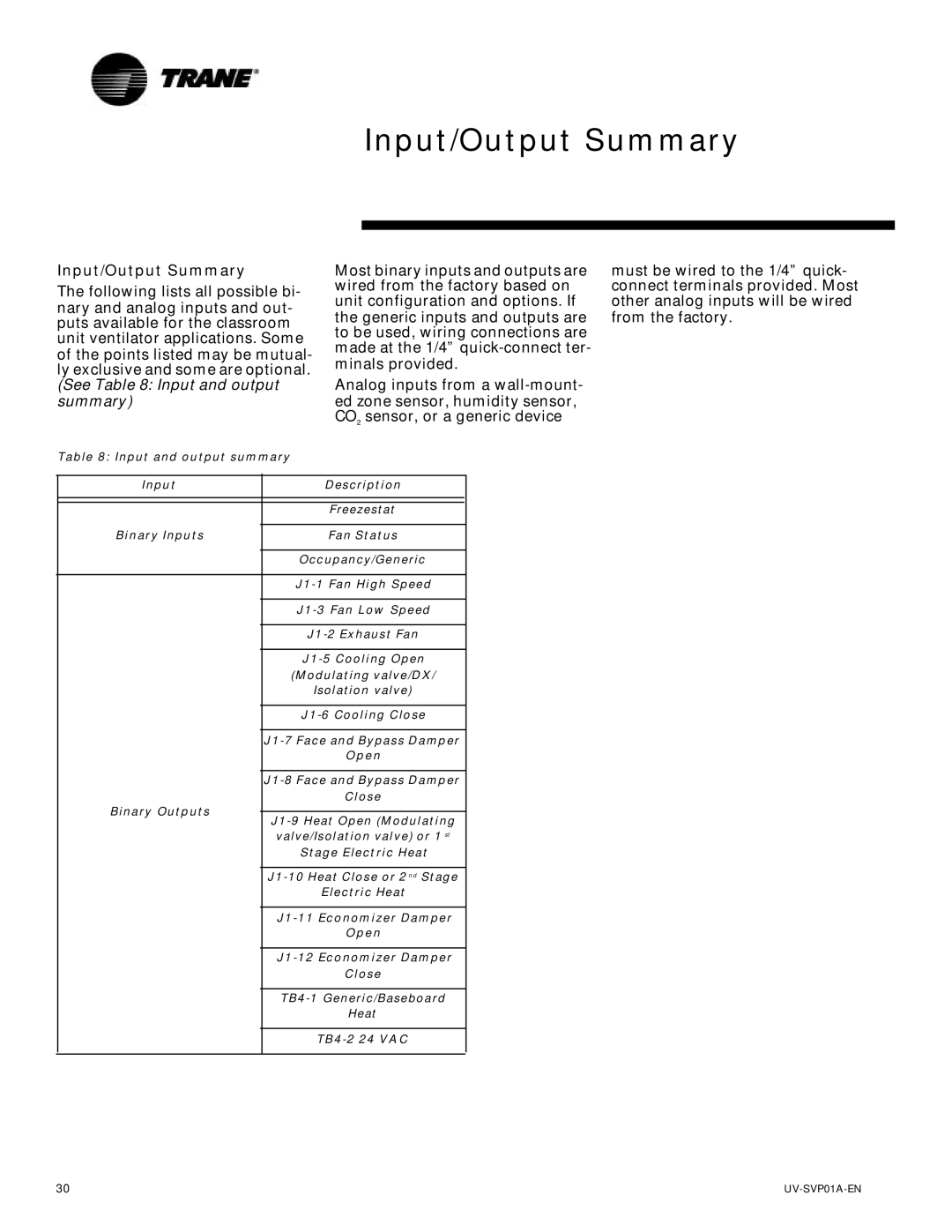
The following lists all possible bi- nary and analog inputs and out- puts available for the classroom unit ventilator applications. Some of the points listed may be mutual- ly exclusive and some are optional. (See Table 8: Input and output
summary)
Table 8: Input and output summary
Most binary inputs and outputs are wired from the factory based on unit configuration and options. If the generic inputs and outputs are to be used, wiring connections are made at the 1/4”
Analog inputs from a
must be wired to the 1/4” quick- connect terminals provided. Most other analog inputs will be wired from the factory.
Input
Binary Inputs
Binary Outputs
Description
Freezestat
Fan Status
Occupancy/Generic
Open
Close
valve/Isolation valve) or 1 st
Stage Electric Heat
Electric Heat
Open
Close
Heat
30 |