Installation and Wiring
Installing the Wall- Mounted Zone Sensor (Optional)
Zone sensor location is an impor- tant element of effective room control and comfort.
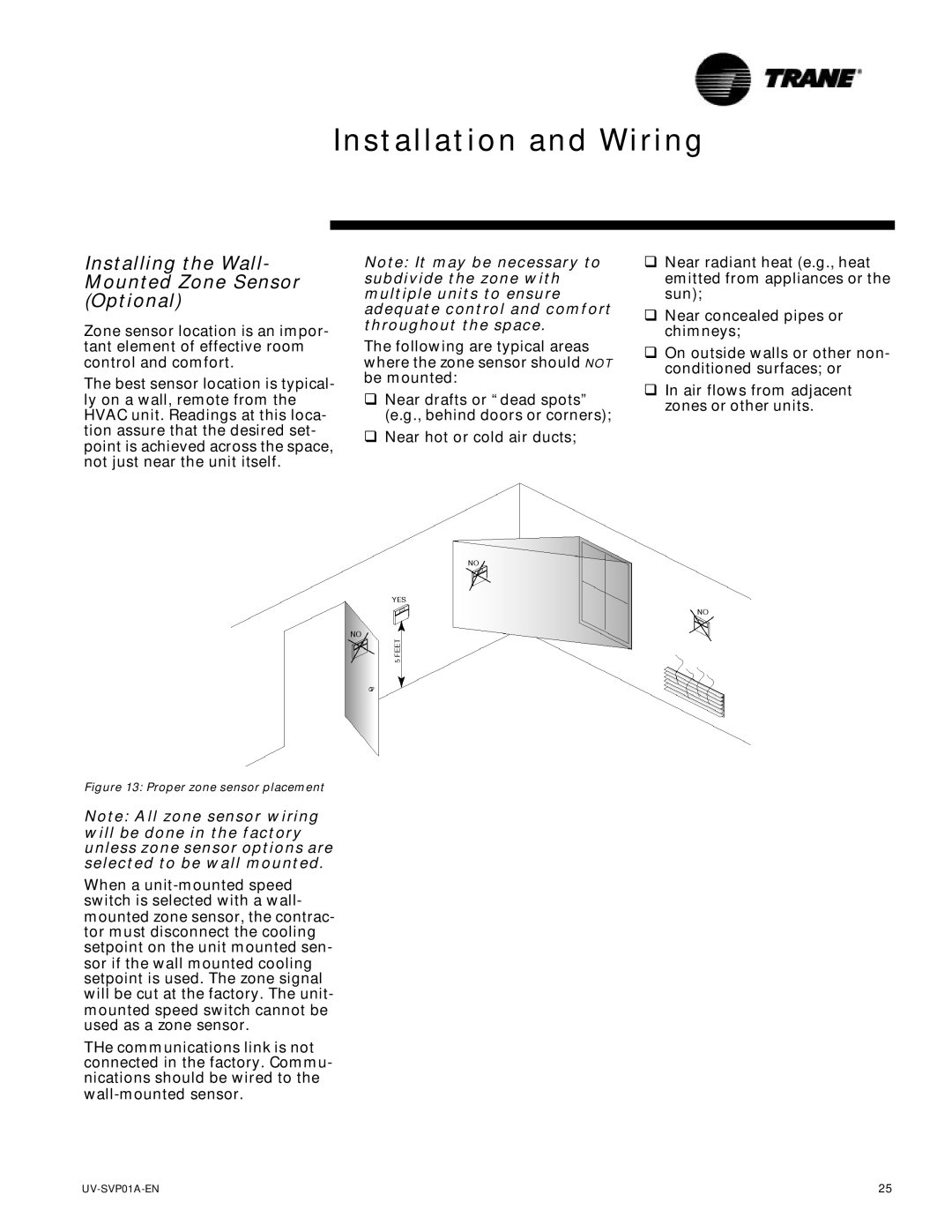
The best sensor location is typical- ly on a wall, remote from the HVAC unit. Readings at this loca- tion assure that the desired set- point is achieved across the space, not just near the unit itself.
Note: It may be necessary to subdivide the zone with multiple units to ensure adequate control and comfort throughout the space.
The following are typical areas where the zone sensor should NOT be mounted:
qNear drafts or “dead spots” (e.g., behind doors or corners);
qNear hot or cold air ducts;
qNear radiant heat (e.g., heat emitted from appliances or the sun);
qNear concealed pipes or chimneys;
qOn outside walls or other non- conditioned surfaces; or
qIn air flows from adjacent zones or other units.
Figure 13: Proper zone sensor placement
Note: All zone sensor wiring will be done in the factory unless zone sensor options are selected to be wall mounted.
When a
THe communications link is not connected in the factory. Commu- nications should be wired to the
25 |