Australia
Fire Indicator Panel Installation & Programming Manual
Tyco Services Fire & Safety
F3200 Product Manual
Tyco Services Fire & Safety END User Liability Disclaimer
Table of Contents
Appendix B
F3200 Installation & Programming Manual Document No LT0122
Appendix a
Amendments
Issue Date Comments ECN
This page is Intentionally Left Blank
Chapter Introduction
1SCOPE
Standards
Associated Documentation
Product
Software
Product History LOG
Hardware
Software History LOG
Glossary of Abbreviations
Glossary of Abbreviations
Glossary of Terminology
This page Intentionally Left Blank
Chapter System Description
Displays
1OVERVIEW
General
Detector Circuits
F3200, Standard Cabinet Front View
F3200 Operator Display Panel
F3200 Small Cabinet
Networking
Power Supply
Outputs
Remote Display & Printer
Small Cabinet
Physical Structure
Standard Cabinet
F3200 Standard Cabinet Internal Layout
F3200, Small CABINET, Maximum Configurations
MAF/PSU
System Structure
PCB Modules
System Structure
RS485 Panel-Link Network Board
INTER-CONNECTION & Structure
Serial Data Flow in the I/O BUS
Example for System with 3 8ZM & 2 8RM
Display Structure Default Mapping
Chapter System Specifications
1GENERAL
Cabinets
Mechanical Specifications
Environmental
6A PSU
Electrical Specifications
Battery Charger & PSU
Mains Supply
Fuses
Battery
Current Consumption
5.1 F3200 Quiescent & Alarm Currents
NDU Quiescent and Alarm Currents
AZC Specifications
Input Specifications
MCP Zener Diode
Typ Max Mode 3 Only
Min Typ Max
Modes 3
IAV = ICL Ieolr
AZC Current Limit Characteristics Modes 1
AZC Current VS Voltage Mode 1 Standard
ACZ Current VS Voltage Modes 3 & 4 LOW Current & Tamper
AZC Current VS Voltage Mode 2 High Current
IAV = ICL+R Ieolr
Bells Relay
Timing
2 MAF/PSU Inputs
Relay Supervision
4 8 Relay Module Supervision
NZ Mode Display Extender Board Inputs
MAF/PSU Inputs
CONTROLLER/DISPLAY Inputs
2 8 Relay Module Outputs
Output Specifications
1 8 Zone Module Outputs
Anc 3/Bells
3 MAF/PSU Outputs Brigade Relays
Ancillary & Bells
Anc 1, Anc
MAF/PSU Outputs
Power Supply Outputs
Battery Backed DC Supply
Spare Parallel Outputs
Non-Battery Backed DC Supply
Rzdu Comms
CONTROLLER/DISPLAY Outputs
5 RS485 Board
CONTROLLER/DISPLAY
Serial Port
Network
E2 Init
Controls
Keypad
Internal Controls
FP0475, FP, 16 Zone LED Display Extender KIT
Displays
Standard Display
Optional Additional Display
Chapter Ordering Information
FP0570,FP,1937-3-1,LOCAL GAS Control STATION,AUTO
Ordering Information
FP0475,16 Zone LED Display Extender KIT,1901-26
FZ3031,KIT,F3200,16 Zone LED DISPLAY,LHS Position
KT0072,KIT,F3200,CARDFRAME Upgrade
Ordering Information
FP0712,FP,F3200 FIP,NO CARDFRAME,24 Zone MAX,6A PSU
LM0092,LOOM 1901-88 Controller to 1ST DISPLAY, FRC, 1.2M
LM0042,LOOM,1888-62,PROG Port to 25 PIN Serial
PA0443,PCB ASSY,1841-18,CONTACT Conversion Module
ME0072,MECH ASSY,1931-70,F3200 Rack MTG Gearplate
Ordering Information NEW Zealand Operation only
Chapter Configuring a FIP
Module Configuration
Battery & Power Supply
General
Page
Battery Size
Battery Test Resistors
Battery Test Resistors
July Issue
Powering AN F3200 from AN External DC Supply
Battery Overcurrent Protection
Battery Overcurrent Protection for Loads Greater than 3A
Programming
Wiring
Current Calculations
3 8 Relay Module
Links on PCB Modules
2 MAF/PSU
COM, NC
Clock crystal timebase check fail
Error Messages During FIP Configuration
Shift reg driver fault
Error messages that can occur on entry to program mode
Chapter Programming
Menu Structure & Parameter Entry
1INTRODUCTION
Base Display Press SET KEY To Enter Menu Structure
This page Left Intentionally Blank
Page
Page
Page
Page
Page
Programming Keys
Recommended Procedure for Configuration & Programming
Save Database
Update RDU Programming
Testing
Checking
View Data Parameters
Operator Accessible Options
SET Menu & Operator Programming Functions
Database Options
Position
Accessing the Database
Initialising the Database
Printing & Saving the Database
DE-ACCESSING the Database
Restoring the Database from a Computer
Saving the Database on a Computer
Verifying a Saved Database
Restoring the Database from a Computer Database Conversion
Program Data MENU, Text & Global Parameters
Access Codes
Prev
Text Entry
Programming Text with the Keypad
Example of Entry of Site Name
Alarm Text Message
Fault Action Text
Text Programming with a PC
Limited to six characters
For V2.06 or earlier software
JEH
MJS BAC
Global Data
FIP MCP
For V2.07 and later software
Auto Test
Cause, Number of Alarms
Bells on for Ffcif Alarm
Ffcif Display cause by default
Alarm Time, Alarm Type, Acknowledge State, Number of Alarms
Brigade Test
Full Cause, Alarm Time, Number of Alarms
Ffcif option Always flash non-MAF alarm LEDs enable/disable
All zones isolated Standby Operation
Printer setup
Country Coder alarm signalling
Daylight saving start/end
NSW, ACT, VIC, SA
Mains/Battery Options
Keys Enable V2.06 or earlier software
COUNTRY/STATE Forward Backward
Global Data
Remote Sounder Silence
Buzzer Mode
Parameter Australian Default NEW Zealand Default
New Zealand Mode
FIP MCP
Programmable Parameters
Issue July
AVF/RAD
Programmable Parameters NEW Zealand only
This page Left Intentionally Blank
Programming System Configuration
Configuring Modules
System Configuration Menu
Page
Page
Page
Mode
Configuring Circuits Azcs
Alarm Text
Instant Alarm Text
For V2.08 or earlier
Time Delays
Mode
AVF/RAD
For D1
Default Settings for Delays
Type 4 circuit with into alarm delay of zero
SAD & Delay Types
Voltage Bands
Reset Delay
AZC Voltage Bands for Modes
Mapping Zones to Leds
Configuring Zones
Mapping to MAF
Status Only Zone
Mapping Zones to Leds
Programming Outputs
Priorities & Evaluation
General CONT’D
Logic Operators
Truth Table
Zone ZN
Logic Operands
Operands Type
Operands Type
Ancillary Relay AR
Zone Range ZR
Relay RL i.e. Module Relay
Network Variables
New Alarm NA
Open Collector OC
Variables
OFF
Timers
Z1A
BFT
ACK
ALM
BEL
NML
NEV
NMA
NMF
Examples of Logic Equations Example 1 Use of Variables
Example 2 Use of Zone Range and Timers In a Deluge System
Examples of Logic Equations
Example 3 Use of Timers
Entering Equations
Example 4 Use of Timer To Make Continuous Pulsing
Not
Example
Not AR RL VL N TM OC ZR NA NV
Enter
Output Logic Programming Menus
Entering an NA Operand
Programming Relays
Controlling Zone Leds
FLT = FLT + SFT
ISO = ISO
RDU Zones
Programming Zone ISOLATE/DE-ISOLATE/RESET Commands
Entering Output Logic Zone Commands
R N I N G
Example Equations
Operation of Output Logic Zone Commands Reset Command
Isolate / Deisolate Commands
Using the ZND and ZNM Tokens
Ancillary Relay Supervision
Relay Supervision
Page
Protocol Type
Rzdu config
RDU
Chapter Installation & Wiring
Use antistatic precautions when handling the PCBs
1INSTALLATION
Cabinet Installation
FIP Cabinet Mounting Details
Cardframe Installation
Module Connection Within a Cardframe
Module Installation
Type format is
LED Display Installation
To install the zone naming label
Zone Labelling
Display Board Connection
Screw Terminal Cable Connection
Field Wiring
Gooseneck Cabling
Mains Wiring
Tyco SU0600 Connection
AZC Wiring
Correct AZC Detector Wiring
SU0600
Examples of Incorrect AZC Wiring
Heavy Load Wiring
MAF Ancillary Relay Wiring
Door Holder Wiring
Plant Relay/Solenoid Wiring
Example of Door Holder Wiring with Supervision
With Supervision of Loop Positive Wiring only
With Supervision of Loop Positive and Negative Wiring
Example of Supervising Multiple Branches of Multiple Loads
Example of Plant Relay Wiring with Supervision
Bell Monitor Rev
MINI-GEN
Microvac and QE90
GEN
Fire Panel
Example of Multiple MINI-GENS with 3 Branches of Speakers
Microvac or QE90
Wiring Ancil 3 to MICROVAC/QE90
Wiring Ancil 3 and 8ZM Input to MICROVAC/QE90
Using Bell Monitor Board on Ancil 3/BELLS Relay
Supervision
Module Relay Wiring
Examples of Module Relay Wiring with Supervision
Dual Polarity Output for STROBES/AVI
Dual Pole Polarity Reversal Output
Direct Coupling
Open Collector Wiring
LED Mimic Displays
Interfacing to Other Equipment
Example of Interfacing to Other EQUIPMENT, Direct Coupling
ASE Installation and Wiring
Cable Limitations
RDU Wiring
RX from the FIP goes to TX on ALL RDUs
Example of RDU Coms Wiring
FP0714 NDU MCP Connection
Slimline NDU FP0714 Wiring
Installation of 19 NDU FP0733
MCP Connection
Chapter Applications
Standard AS1668 Module Panel Layout
AS1668 AIR Conditioning Control
Circuits & Zones FIP End Inputs
F3200 with Typical AS1668 Panel 10 Units
Circuits & Zones
With a Rotary SWITCH, on is B1 INSTANT, OFF is B2 Alarm
With a Rotary SWITCH, on is B1 INSTANT, OFF is Fault
Fan Inputs
For two AZC inputs
Relays
Example of FAN RUN & Fault Wiring to AZC
TWO Open Collector O/PS PER FAN Ref
Wiring of FAN Control Leds
Leds
Three Open Collector O/PS PER FAN Ref
5 AS1668 Control Module & Drawings
Outputs RUN Fault Stopped OC1
Control Module CCT
1945-1-2 PA0727
1945-1-3 PA0728
1945-1-4 PA0728
GAS Flood
Logic & Configuration
Open Collector LEDs
Timer
Configure Circuits
Configure Zones
MAF LED
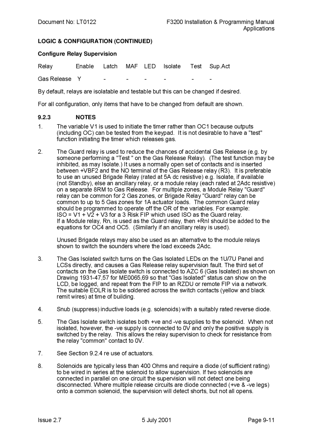
Configure Relay Supervision
USE of Actuators
Connecting Multiple Actuators
Function Illuminate Tone
AVI Signs
Drawings
Function Input Lamps
DIL SW DIL Sw Lk1,2 Lk3 Lk6 Off
GAS Flood Logic Diagram
Local GAS Control STATION, Front View
Wiring Multiple Supervised 2 Stage Signs
Wiring Multiple Supervised System Inoperative Signs
Page
Page
Loop Resistance of 800 Ohm to 2000 Ohm
SUB FIP Monitoring
Loop Resistance Less than 150 Ohms
Loop Resistance of 150 Ohm to 800 Ohm
Connection
Example of SUB-FIP Monitoring Using 2 Azcs
Example of SUB-FIP Monitoring Using 1 AZC
Example of SUB-FIP Monitoring for Resistance Case 1 only
References
Fire Detection in Hazardous Areas Explosive Atmospheres
Maximum Capacitance & Inductance PER is Circuit
Intrinsically Safe Detection
Isolated Repeaters
GAS Group MAX. Capacitance MAX. Inductance
Capacitance & Inductance PER I.S. Detector
Capacitance Inductance Resistance FW only
MR301TEX HPO
Relay or Open Collector
F3200 is Circuit Using 6-TERMINAL Repeaters
3.2 6 Terminal Isolated Repeater
Programming & Limitations
Terminal Isolated Repeater
ZAU401
3.3 4 Terminal Isolated Repeater with Zone Adaptor Unit
F3200 with ZAU401 & 4 Terminal is Repeater
Terminal Isolated Repeater with Zone Adaptor Unit ZAU401 REV
See Text SHORT-CIRCUITING Detectors with 4 Terminal Repeater
3.4 4 Terminal Isolated Repeater Alone
Terminal Isolated Repeater Alone
USE of Normally Closed Contacts
Normally Closed Contact Wiring to F3200 AZC
R N I N G
Connecting the S231I+ or S231F+ Using ZAU401 REV
Special Connections to Detectors
This page Intentionally Left Blank
Chapter ALIGNMENT, Adjustment Placing Into Operation
VR3
Alignment & Adjustment
VR2
VR1
Placing Into Operation
Step
Power UP
10.2.2
Cabinet & General
Commissioning Checklist
Pcbs & Wiring
Serial Number Test Passed
Power Supply
Operation
Chapter Network Programming
Network Application Overview
11.1INTRODUCTION
PANEL-LINK Network
Intended usages for the Panel-Link are
Network Application Overview
Network MAF Status
Programming Methods
Data Filters the SID List & Groups List
F3200 Network Programming Menu Structure
F3200 output logic tokens affected by network MAF status
BLI
Programming Methodology
NETPG2 Options
Network Configuration Menu
NETPG1 Options
NETPG4 Options
NETPG3 Options
Ack broadcasts to specific SID
Mode B
NETPG5 Options
Log events Yes/No
SID Configuration
SID Menu ONE
Link RX Yes/No
SID Menu TWO
Options Under NETMAF3
Network MAF Configuration
Options Under NETMAF1
Options Under NETMAF2
RX Time/Date Yes/No
NET Commands
ACK time 1-250 seconds
Work time 1-250 seconds
Dedicated TX SID
NET Ffcif Configuration
Options under FFCIF1 TX alarms Yes/No
TX ack cmds
Ffcif Configuration
Options under FFCIF2 TX iso/reset cmds
Remote ACK Yes/No
TX relay controls Yes/No
Network Event Configuration
Transmit event updates Yes/No
Options under Events1 Transmit events Yes/No
Sys event text tx Yes/No
Network Event Configuration
Options under Events2 Zone/relay cmd text tx Yes/No
Zone/relay event text tx Yes/No
Max COS TX rate 0-250 seconds
TX enabled Yes/No
Network Logic Variables
TX refresh rate 0-255 seconds
Fast TX rate
Status refresh enabled Yes/No
NET Status Refresh
TX rate
MAF board present/not present
NDU Operation
Programming an NDU
NDU Operation
Network SID Configuration per SID
Default Values for PANEL-LINK Variables
Parameters Default Network Setup
Parameters Default Network Event Config
This page Intentionally Left Blank
Chapter NEW Zealand Operation
NZ Display Extender Board
12.1GENERAL
NEW Zealand Extender Termination Board
Display Extender Board
Manual Callpoint MCP
NZ Mode MCP Wiring for NDU MAF Board
NZ Mode MCP Wiring for Slimline NDU
Programmable Options
Programmable Options
Logic Tokens
System States & Indications
System States & Indications
Network Parameter Programming
SID List
Network Ffcif Configuration
Mimic Display
Installation NZ Display Extender Board Brigade Displays
Active Display
Display Extender Board Miscellaneous Termination
NDU Cabinet External Mi mic Dis play C abinet
1 Remote Plan Mimic Display
NDU Cabinet
2 Remote Mimic Using Picture Frame Display Cabinet
NDU Cabinet
NDU Cabinet
Wiring of NDU to PFD Active Display
BSR
This page Intentionally Left Blank
Chapter Tandem LCD Mode
Tandem LCD Mode
Table I Grinnell Detector Range
Appendix A1 Compatible Actuating Devices Detectors
Simplex Detectors
Tyco Detectors
Hochiki Detector Range
Grinnell Detector/Base Range
DET/REM IND
Other Detectors
Actuating Device Compatibility
High Current Detectors
Appendix A2 Programming for Detector Type
Hard Contact Detectors
Delay Type
Appendix A2
Remote LEDs
A-8 July Issue
Table IV Tyco Detector Range
ZAU401 Zone Adaptor Unit REV 2 B2 B2
Appendix B
F3200 Configuration Sheets
This page Intentionally Blank
User Initials
Site Name 40 Characters Maximum
System Options
PSU/BATTERY Options
NEW Zealand Mode Options
Auto Test
XOR Not
Default is ALL Enabled ALL Disabled
Spklr FSW
Alarm Text Names
RDU Parameters
PSW
Time Difference Hour Minute
Start END Month Hour Minute
AZC Programming Field Wiring
F3200 AZC Configuration
F3200/NDU Zone Configuration
8ZM OUT Function Name Logic Equation PUT
Function & Logic Equation
8RM RLY Programming Text Name Characters Defaults
F3200 Relay Configuration
8RM no Relay Name Logic Equation
F3200/NDU Relay Functions Logic Equations
8RM no Relay Name Field Wiring
F3200 Relay Field Wiring
Logical Relay
Alarm Fault Isolate Logic Equation
TIMER/VARIABLE NETVARS/ZONE CMD/SNA Logic Equation
Network Ffcif Config
Network Setup
Network MAF Config
Network Command Config
F3200/NDU Configuration Network SID List Configuration
B-18 July Issue