Planning the Installation
PV Array
PV String #1
G
PV String #2
G
Main Utility |
|
Service Panel | |
L1 | L2 |
NEUTRAL | |
| Neutral |
| |
| Ground |
GROUND | Bond |
| |
G | G |
Xantrex GT Inverter
Wiring Box
GND bar
| G | Primary | |||||||
| Earth | ||||||||
|
| ||||||||
AC/DC Disconnect |
| Ground | |||||||
Switch |
|
|
|
|
|
|
|
|
|
|
|
|
|
|
|
|
|
| |
|
|
|
|
|
|
|
|
|
|
|
|
|
|
|
|
|
|
|
|
|
|
|
|
|
|
|
|
|
|
|
|
|
|
|
|
|
|
|
|
|
|
|
|
|
|
|
|
|
|
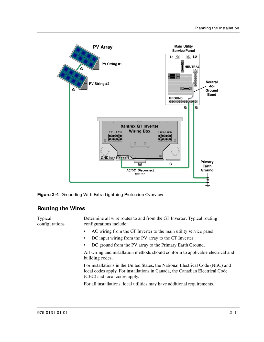
Figure 2-4 Grounding With Extra Lightning Protection Overview
Routing the Wires
Typical | Determine all wire routes to and from the GT Inverter. Typical routing |
configurations | configurations include: |
| • AC wiring from the GT Inverter to the main utility service panel |
| • DC input wiring from the PV array to the GT Inverter |
| • DC ground from the PV array to the Primary Earth Ground. |
| All wiring and installation methods should conform to applicable electrical and |
| building codes. |
| For installations in the United States, the National Electrical Code (NEC) and |
| local codes apply. For installations in Canada, the Canadian Electrical Code |
| (CEC) and local codes apply. |
| For all installations, local utilities may have additional requirements. |