Installation
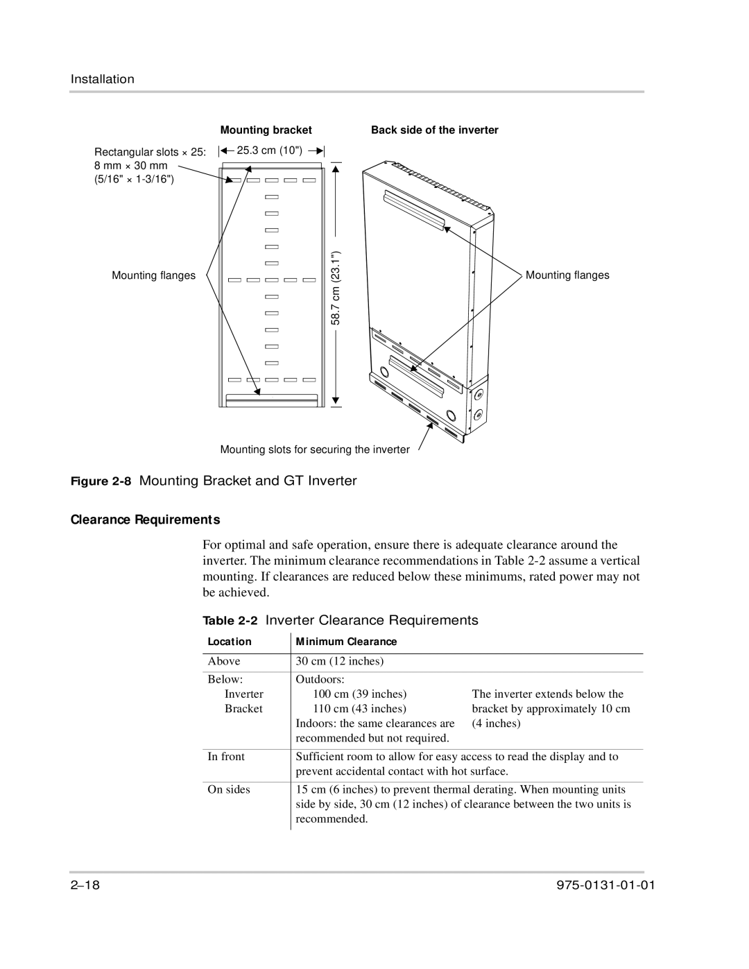
Rectangular slots × 25: 8 mm × 30 mm (5/16" ×
Mounting flanges
Mounting bracket | Back side of the inverter |
![]()
![]() 25.3 cm (10")
25.3 cm (10")
58.7 (23.1")cm
Mounting flanges
Mounting slots for securing the inverter
Figure 2-8 Mounting Bracket and GT Inverter
Clearance Requirements
For optimal and safe operation, ensure there is adequate clearance around the inverter. The minimum clearance recommendations in Table
Table 2-2 Inverter Clearance Requirements
Location | Minimum Clearance |
| |
|
|
| |
Above | 30 cm (12 inches) |
| |
|
|
| |
Below: | Outdoors: |
| |
• | Inverter | • 100 cm (39 inches) | The inverter extends below the |
• | Bracket | • 110 cm (43 inches) | bracket by approximately 10 cm |
|
| Indoors: the same clearances are | (4 inches) |
|
| recommended but not required. |
|
|
| ||
In front | Sufficient room to allow for easy access to read the display and to | ||
|
| prevent accidental contact with hot surface. | |
|
| ||
On sides | 15 cm (6 inches) to prevent thermal derating. When mounting units | ||
|
| side by side, 30 cm (12 inches) of clearance between the two units is | |
|
| recommended. |
|
|
|
|
|