Mounting the Inverter
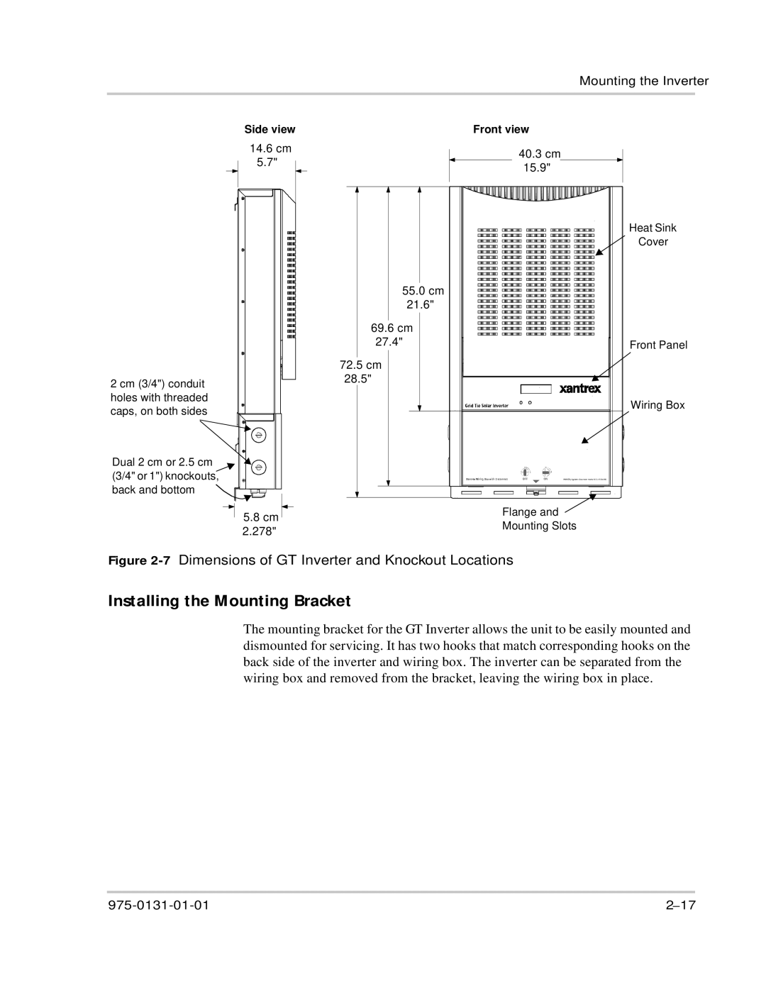
2 cm (3/4") conduit holes with threaded caps, on both sides
Side view
14.6 cm |
5.7" |
55.0 cm 21.6"
69.6cm
27.4"
72.5cm
28.5"
Front view
40.3 cm |
15.9" |
Heat Sink |
Cover |
Front Panel |
Wiring Box |
Dual 2 cm or 2.5 cm (3/4" or 1") knockouts, back and bottom ![]()
5.8 cm 2.278"
Flange and Mounting Slots
Figure 2-7 Dimensions of GT Inverter and Knockout Locations
Installing the Mounting Bracket
The mounting bracket for the GT Inverter allows the unit to be easily mounted and dismounted for servicing. It has two hooks that match corresponding hooks on the back side of the inverter and wiring box. The inverter can be separated from the wiring box and removed from the bracket, leaving the wiring box in place.