Replacing Parts
| Front view | Back view | |||||||||
|
|
|
|
|
|
|
|
|
|
|
|
|
|
|
|
|
|
|
|
|
|
|
|
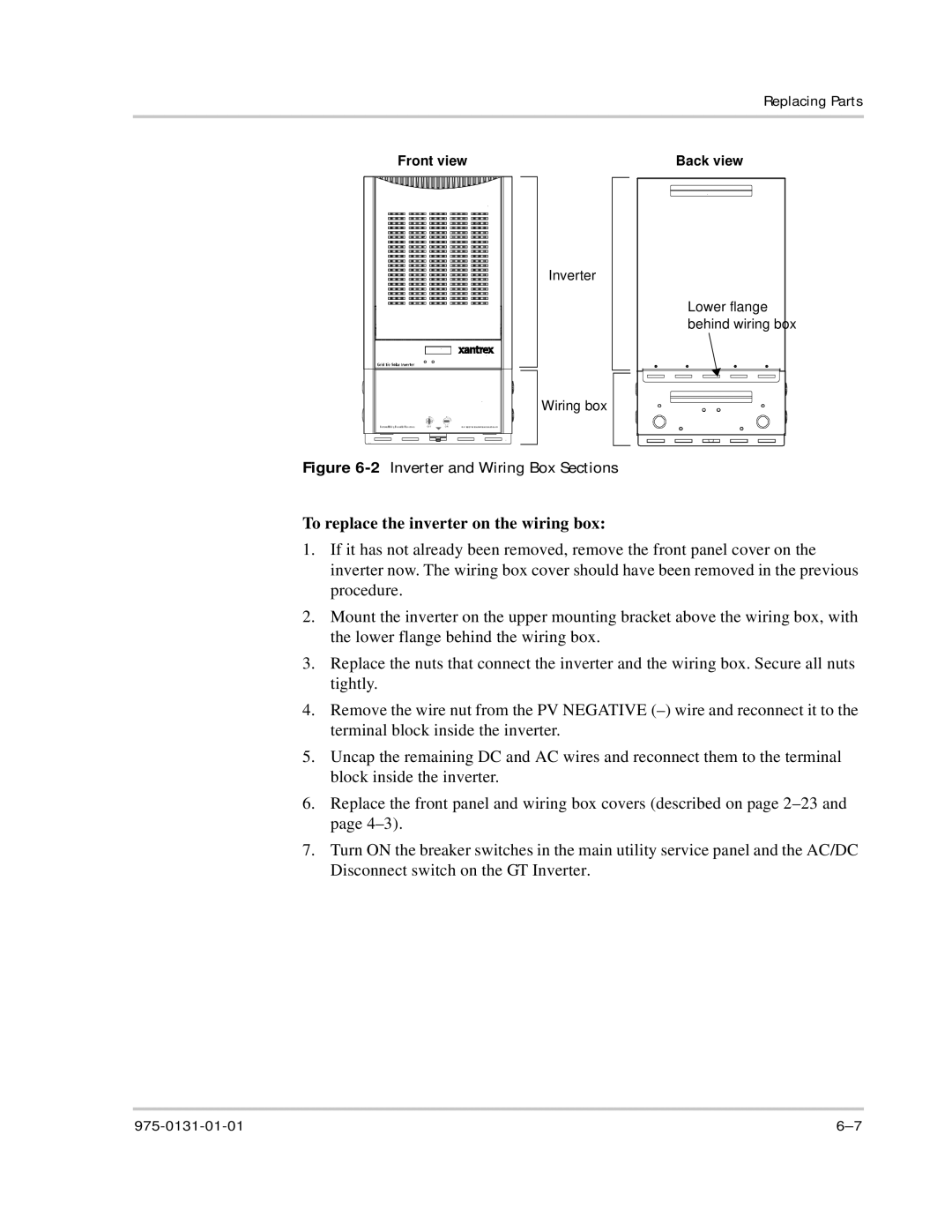
Inverter
Wiring box
Lower flange behind wiring box
Figure 6-2 Inverter and Wiring Box Sections
To replace the inverter on the wiring box:
1.If it has not already been removed, remove the front panel cover on the inverter now. The wiring box cover should have been removed in the previous procedure.
2.Mount the inverter on the upper mounting bracket above the wiring box, with the lower flange behind the wiring box.
3.Replace the nuts that connect the inverter and the wiring box. Secure all nuts tightly.
4.Remove the wire nut from the PV NEGATIVE
5.Uncap the remaining DC and AC wires and reconnect them to the terminal block inside the inverter.
6.Replace the front panel and wiring box covers (described on page
7.Turn ON the breaker switches in the main utility service panel and the AC/DC Disconnect switch on the GT Inverter.