Front Panel Display Screens and What They Mean
Front Panel Display Screens and What They Mean
The front panel display shows different message screens during different modes of operation (Startup, Normal, Offline, and Fault). All single units display a basic set of message screens; multiple unit systems display additional screens in Normal Operation and Offline modes.
In addition there are Special message screens that may appear in any operational mode. All of these message screens are described in more detail in the following tables.
Startup Mode
During startup, the GT Inverter displays three message screens on its front panel LCD. These screens appear in the following order (Table
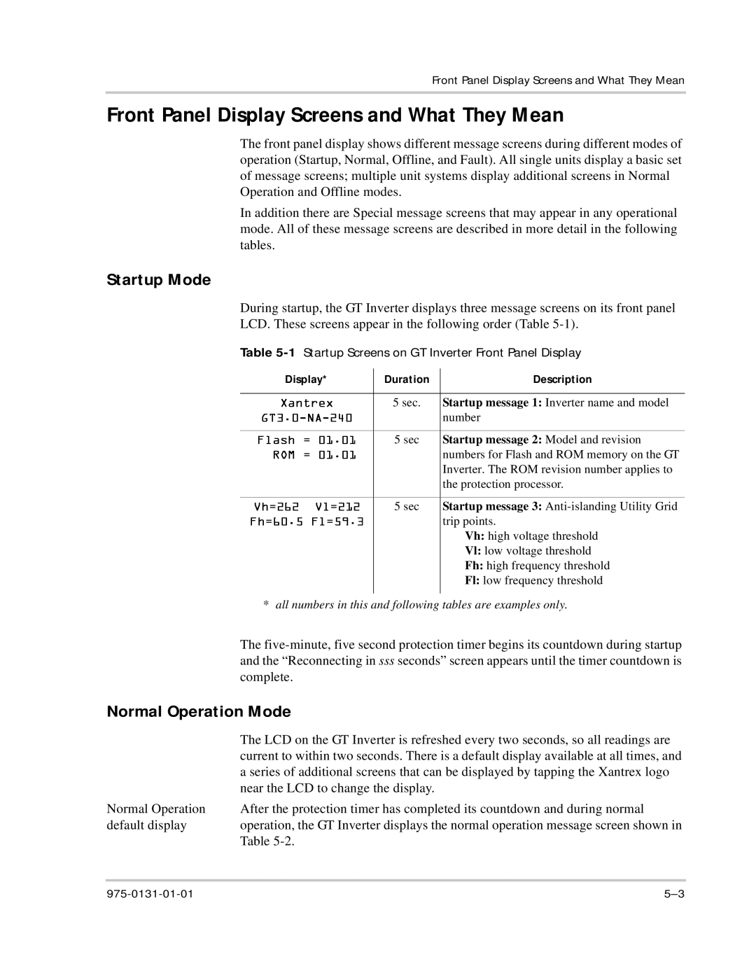
Table 5-1 Startup Screens on GT Inverter Front Panel Display
Display* | Duration | Description |
|
|
|
| 5 sec. | Startup message 1: Inverter name and model |
|
| number |
|
|
|
| 5 sec | Startup message 2: Model and revision |
|
| numbers for Flash and ROM memory on the GT |
|
| Inverter. The ROM revision number applies to |
|
| the protection processor. |
|
|
|
| 5 sec | Startup message 3: |
|
| trip points. |
|
| Vh: high voltage threshold |
|
| Vl: low voltage threshold |
|
| Fh: high frequency threshold |
|
| Fl: low frequency threshold |
|
|
|
* ll numb rs in this and following tables are examples only.
| The |
| and the “Reconnecting in sss seconds” screen appears until the timer countdown is |
| complete |
| Xantrex |
Normal Operation | |
| TheFlashLCD on the GT Inverter is refreshed every two seconds, so all readings are |
| currentROMto within=01.01two seconds. There is a default display available at all times, and |
| a series of additional screens that can be displayed by tapping the Xantrex logo |
| near the LCD to change the display. |
Normal Operation | AfterVh=262Vl=212the protection timer has completed its countdown and during normal |
default display | operation,Fh=60.5Fl=59.3the GT Inverter displays the normal operation message screen shown in |
Table