Wiring the Inverter
Accessing the Wiring Terminals
You must remove the GT Inverter wiring box cover to access the terminal blocks, ground bar and communications ports (for inverters in parallel).
To remove the wiring box cover:
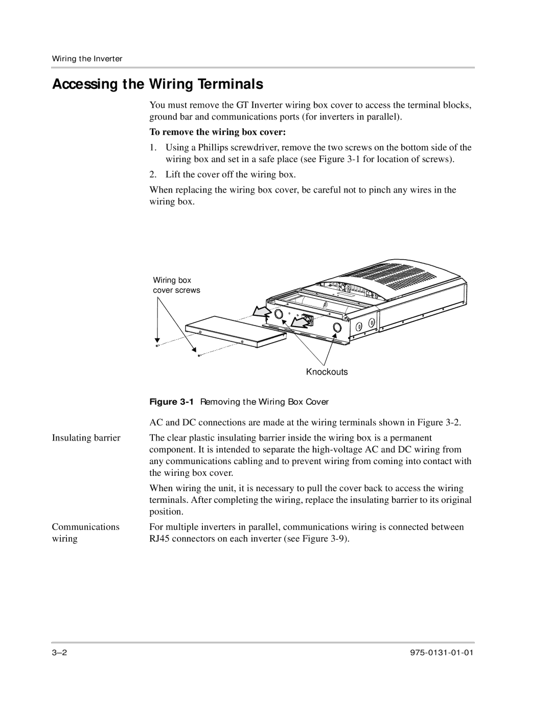
1.Using a Phillips screwdriver, remove the two screws on the bottom side of the wiring box and set in a safe place (see Figure
2.Lift the cover off the wiring box.
When replacing the wiring box cover, be careful not to pinch any wires in the wiring box.
Wiring box cover screws
| Knockouts |
| Figure |
| AC and DC connections are made at the wiring terminals shown in Figure |
Insulating barrier | The clear plastic insulating barrier inside the wiring box is a permanent |
| component. It is intended to separate the |
| any communications cabling and to prevent wiring from coming into contact with |
| the wiring box cover. |
| When wiring the unit, it is necessary to pull the cover back to access the wiring |
| terminals. After completing the wiring, replace the insulating barrier to its original |
| position. |
Communications | For multiple inverters in parallel, communications wiring is connected between |
wiring | RJ45 connectors on each inverter (see Figure |