Manuals
/
Xerox
/
Computer Equipment
/
Switch
Xerox
NS-2260 operation manual Port-basedVLAN, Click Add : to create a new VLAN group
Models:
NS-2260
1
117
149
149
Download
149 pages
61.72 Kb
114
115
116
117
118
119
120
121
<
>
Specification
Install
Dimension
Radius client configuration
Reset System
Management Setup
Enter Transfer ->Send File command
Appendix A: Factory Default Settings
Max bridge transmit delay bound Port Security
Per port control settings
Page 117
Image 117
5.5.7.1
Port-based
VLAN
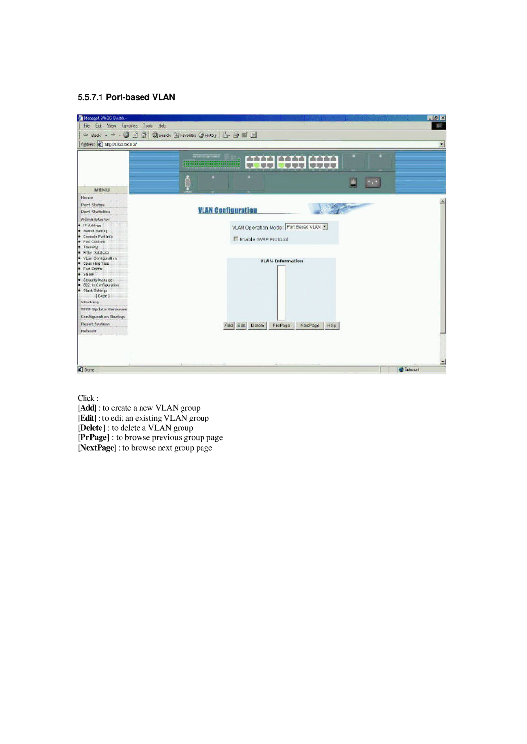
Click :
[
Add
] : to create a new VLAN group
[
Edit
] : to edit an existing VLAN group
[
Delete
] : to delete a VLAN group
[
PrPage
] : to browse previous group page
[
NextPage
] : to browse next group page
Page 116
Page 118
Page 117
Image 117
Page 116
Page 118
Contents
Operation Manual
NS-2260 Optional 100FX Modules
Optional Gigabit Modules
TRADEMARKS
NOTICE
CISPR A COMPLIANCE
2. Installation and Management
Table of Contents
3. Console and Telnet Operation
1. Introduction
5. Web Management
4. SNMP Management
Appendix A: Factory Default Settings
6. Update Firmware from Console
1.1 Introduction
1. Introduction
1.2 Features
1.3 Hardware Specifications
Power Input Rating
Dimension
Power Consumption
Operating temperature : 0 ~ 50oC
1.4 Software Specifications
Management Objects
1.4.1 Management Objects
Console TelnetWeb
SNMP
Management Objects
1.4.2
Console TelnetWeb
SNMP
LACP disabled
LACP enabled
Rules of trunking
IP Multicast address
1.5.2 IP Multicast Function
IGMP
1.5.3 MAC Address Filtering Function
IGMP Snooping
Multicast Forwarding
1.5.5 Port Security
1.5.4 Static MAC Address
1.5.6.1 Port-basedVLAN
1.5.6 VLAN Function
1.5.6.2 IEEE 802.1Q VLAN Tag-basedVLAN
1.5.6.3 Protocol-basedVLAN
1.5.7 Spanning Tree Protocol
Per port control settings
1.5.8 Port Sniffer Function
STP related parameters
Spanning tree port states
Page
1.5.9 QoS Priority Function
Outgoing Service Policy
Priority Classification Methods
1.5.10 802.1X Port-BasedNetwork Access Control
Radius client configuration
Enable 802.1X protocol
Per-port802.1X mode setting
Misc. configuration
2.1 Panel Description 2.2 AC Power Supply
2. Installation and Management
2.3.1 10/100TX Ports
2.3 Network Switched Ports
Specifications Port Type
Port Number
100FX Module Installation
2.3.2 100FX Modules
Working Connectors
JP1 setting
Part Number
2.3.3 Gigabit Ports and Modules
Specifications
Giga Port Module Installation steps
2.4 Rack Mounting
LED Name
2.5 LED Indicators
State
Interpretation
2.6 Cooling Fans
2.7 Management Setup
2.7.1 Setup for Out-of-bandConsole Management
2.7.3 Quick Guide to Configure Switch IP Address
2.7.2 Setup for In-bandManagement
Main Menu >Switch Static Configuration
>Administration Configuration >IP Configuration
3. Console and Telnet Operation
Power-on Self-testConsole message
Cold Start
Direct Console Management
Login Prompt
Telnet Management
>telnet
Protocol Related Configuration
3.1 Main Menu
Status and Counters Reboot Switch
TFTP Update Firmware Logout
Action menu
Managed 24+2G Switch: Switch Configuration
3.2 Switch Static Configuration
Port Configuration
Trunk Configuration VLAN Configuration
Managed 24+2G Switch: Port Configuration
3.2.1 Port Configuration
Auto : Port auto negotiation mode control setting
Options - Yes=Enable, No=Disable
Options - On=Enable, Off=Disable
DISABLE The group is disabled STATIC Normal trunk
3.3.3.1 VLAN Configure
3.3.3 VLAN Configuration
Managed 24+2G Switch: VLAN Configuration
VLAN Configure
Per port control settings PVID : Port VID
Create a Port-basedVLAN group
3.3.3.2 Create a VLAN Group
Create an 802.1Q VLAN
3.3.3.3 Edit / Delete a VLAN Group
Managed 24+2G Switch: Group Sorted Selection
3.3.3.4 Groups Sorted Mode
Example to edit Vlan2 group
Group Sorted : Sorted_by_Name
3.3.4.1 MAC Age Interval
3.3.4 Misc Configuration
Managed 24+2G Switch: Misc Configuration
Max bridge transmit delay bound Port Security
3.3.4.2 Broadcast Storm Filtering
3.3.4.3 Max Bridge Transmit Delay Bound
3.3.4.4 Port Security
3.3.4.6 Hash Algorithm
3.3.4.5 Collision Retry Forever
3.3.5.1 Change Username
3.3.5 Administration Configuration
Managed 24+2G Switch: Device Configuration
Change Password Device Information
3.3.5.3 Device Information
3.3.5.2 Change Password
Managed 24+2G Switch: Password Configuration
Managed 24+2G Switch: Device Configuration
3.3.5.4 IP Configuration
3.3.6 Port Sniffer Configuration
3.3.7 Priority Configuration
3.3.7.1 Static Priority
All High before Low = high priority packets first
3.3.7.2 802.1p Priority
3.3.8.1 Static MAC Address
3.3.8 MAC Address Configuration
Managed 24+2G Switch: MAC Address Configuration
Filtering MAC Address Previous Menu
Select one static MAC address to edit or delete
Add static MAC address
3.3.8.2 Filtering MAC Address
3.4.1 STP
3.4 Protocol Related Configuration
Managed 24+2G Switch : Spanning Tree Protocol
STP Enable
System Configuration
STP Enable
Perport Configuration
3.4.2.1 System Options
3.4.2 SNMP
Add/Edit a Community String
3.4.2.2 Community Strings
Add/Edit a trap manager
3.4.2.3 Trap Managers
3.4.4 IGMP
3.4.3 GVRP
Managed 24+2G Switch: GVRP Configuration
GVRP : Enabled
3.4.5 LACP
3.4.5.1 Working Port Setting
3.4.5.2 State Activity
3.4.6
3.4.5.3 LACP Status
3.4.6.2 802.1X System Configuration
3.4.6.1 Enable 802.1X Protocol
Managed 24+2G Switch: 802.1x System Configuration
action-><Edit> <Save> <Quit>
Managed 24+2G Switch: 802.1x Port Status
3.4.6.3 802.1X Per Port Configuration
Force Unauth= Fu, Force Au=Fa, Auto=Au, None=No
Port Status
3.4.6.4 802.1X Misc. Configuration
3.5 Status and Counters
3.5.1 Port Status
3.5.2 Port Counters
3.5.3 System Information
3.6 Reboot Switch
3.6.2 Default
3.6.1 Restart
3.7 TFTP Update Firmware
Main Menu >Reboot Switch >Restart
3.7.1 TFTP Update Firmware
Main Menu >Reboot Switch >Default
3.7.2 TFTP Restore Configuration
3.7.3 TFTP Backup Configuration
4. SNMP Management
Port MIB-2Objects
4.2 SNMP MIB-2and Private MIB
Set/Get
Value Options
Private MIB Objects
Set/Get
Value Options
Trap Name
4.3 SNMP Traps
RFC1157
Event of Trap Generated
Best Display Resolution 1024 x 768 pixels up
5. Web Management
Web Browser
Set IP Address for the device unit
Factory default IP address :
5.1 Start Browser Software and Making Connection
_ Administrator _ Stacking _ TFTP Update Firmware
5.2 Web Management Home Overview
_ Configuration Backup _ Reset System _ Reboot
_ Menu _ Port Status _ Port Statistics
Config / Atual
5.3 Port status
Atual : current flow control status
5.4 Port Statistics
_ Switch settings
5.5 Administrator
_ VLAN configuration _ Spanning tree
_ Security Manager _ Stack Settings
5.5.1 IP Address
5.5.2.1 Basic Information
5.5.2 Switch Setting
5.5.2.2 Module Info
5.5.2.3 Advanced
Apply : confirm and apply the settings
Enable : retry forever for collision situation
Default : use default values for all settings
CRC-Hash :use CRC-hashmethod
5.5.3 Console Port Information
Parity Check : none Stop Bits :
Flow control : none
5.5.4 Port Controls
Half = Half duplex
5.5.5 Trunking
5.5.5.1 Aggregator settings
5.5.5.2 Aggregator Information
No active group configured
The following pages illustrate three examples
Two Static Trunking groups are configured
Page
5.5.5.3 State Activity
Per port LACP mode
Click Button Apply : Apply the changes
Control setting
5.5.6.2 Static MAC Address
5.5.6.3 MAC Address Filtering
Port Based VLAN
5.5.7 VLAN configuration
Click Add : to create a new VLAN group
5.5.7.1 Port-basedVLAN
Edit : to edit an existing VLAN group
Delete : to delete a VLAN group
VLAN name : Name of the VLAN group
Group ID : Unique ID for the group
Click Apply to confirm the changes
5.5.7.2 802.1Q VLAN
Add a new VLAN
Remove - remove a member port
Tag : outgoing frames with VLAN-Tagged
Untag : outgoing frames without VLAN-Tagged
Ingress Filtering Rule 2 : Drop Untagged Frame
5.5.8 Spanning Tree
This page shows an example of STP port status
STP State : Enable or disable STP function
STP parameters settings
messages. Valid values : 1 ~
Refer to Chapter 1 for STP Parameter Descriptions
STP port status
STP port parameters settings
5.5.9 Port Sniffer
SNMP Parameters
5.5.10 SNMP
SNMP Managers
SNMP Trap Managers
Assign/Change password : Type the new password
5.5.11 Security Manager
5.5.12 802.1X Configuration
System Configuration
5.5.12.1 802.1X PerPort Configuration
5.5.12.2 802.1X Misc Configuration
5.5.13 Stack Settings
Username - The login username of the member unit
Configure other members in the stack
Password- The password of the member unit
Stack Name - Give a name to this stack
5.6 Stacking
Close Stack View window to exit stack management
Stop Auto Refresh : Disable auto refresh
5.7 TFTP Update Firmware
1.Start your TFTP server
5.Click Apply to start the download operation
7. Reboot the system
5.8.1 TFTP Restore Configuration
5.8 Configuration Backup
5.8.2 TFTP Backup Configuration
Click Reset to start the operation
5.9 Reset System
Click Reboot to start operation
5.10 Reboot
4.Enter Transfer ->Send File command
6. Update Firmware from Console
Cases to update firmware from console
Setup 1K Xmodem on Hyper Terminal
Appendix A: Factory Default Settings
Forward Delay Time
802.1X Function Settings