Manuals
/
Xerox
/
Computer Equipment
/
Switch
Xerox
NS-2260
operation manual
Spanning Tree
Models:
NS-2260
1
123
149
149
Download
149 pages
61.72 Kb
120
121
122
123
124
125
126
127
Specification
Install
Password
Default
LED Indicators
Login
Administrator
Misc. configuration
Reset System
Management Setup
Page 123
Image 123
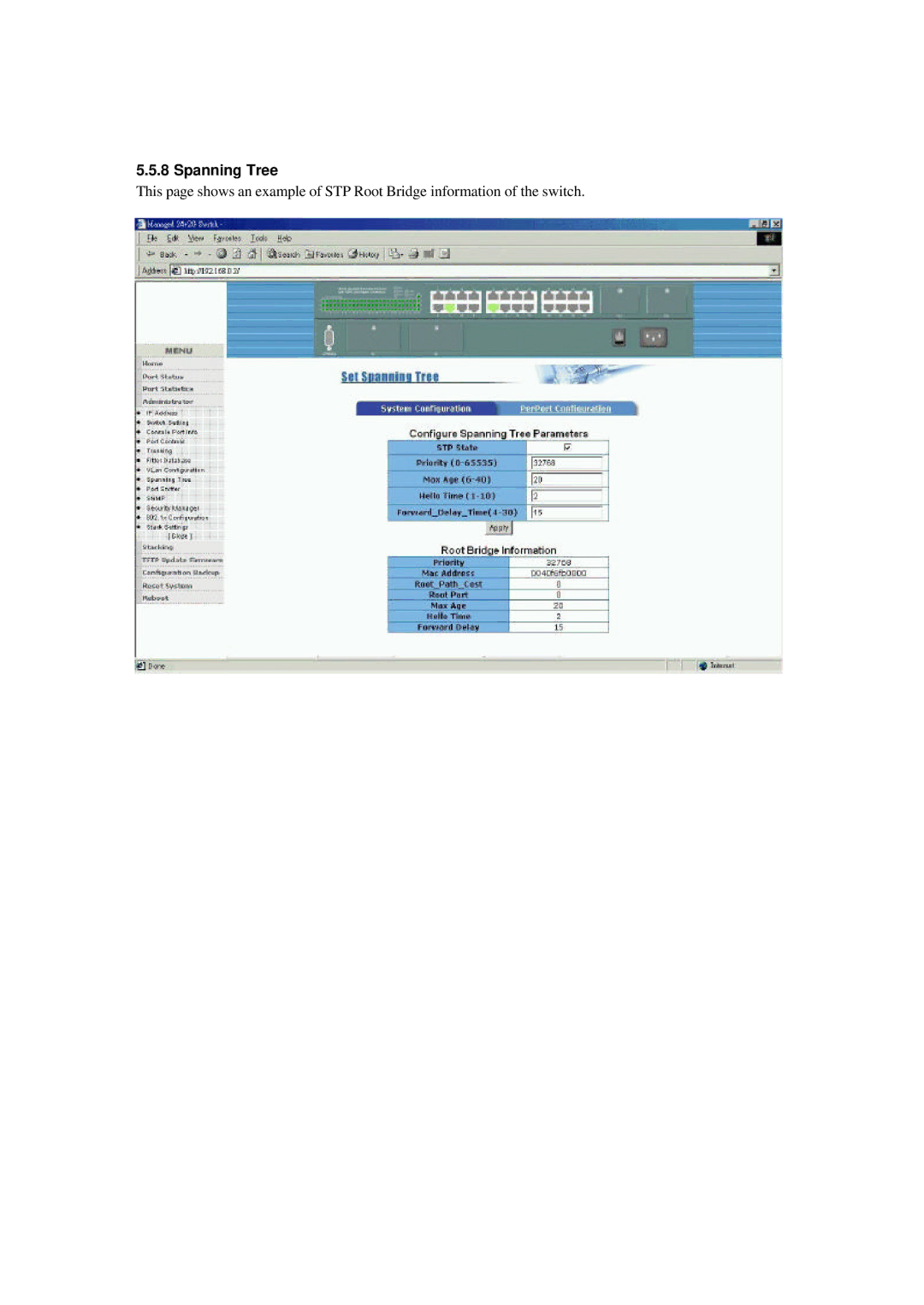
5.5.8 Spanning Tree
This page shows an example of STP Root Bridge information of the switch.
Page 122
Page 124
Page 123
Image 123
Page 122
Page 124
Contents
NS-2260 Optional 100FX Modules Optional Gigabit Modules
Trademarks
Table of Contents
Installation and Management
Console and Telnet Operation
Snmp Management
Appendix a Factory Default Settings
Update Firmware from Console
Introduction
Introduction
Supports Ethernet frame length up to 1522 bytes
Features
Gvrp
Hardware Specifications
Speed status
Software Specifications
Management Objects Console TelnetWeb
Management Objects
Type Trap Event
Trap Events
Lacp disabled
Lacp enabled
Rules of trunking
IP Multicast address
IP Multicast Function
Igmp
Igmp Snooping
Multicast Forwarding
MAC Address Filtering Function
Port Security
Static MAC Address
Port-based Vlan
Vlan Function
Ieee 802.1Q Vlan Tag-based Vlan
Protocol-based Vlan
Spanning Tree Protocol
Port Sniffer Function
Per port control settings
STP related parameters
Spanning tree port states
Page
Outgoing Service Policy
QoS Priority Function
Priority Classification Methods
10 802.1X Port-Based Network Access Control
Enable 802.1X protocol Radius client configuration
Per-port 802.1X mode setting
Misc. configuration
Panel Description AC Power Supply
Installation and Management
Speed Compliance Cables Distance
Network Switched Ports
Port Number Label Specifications Port Type
1 10/100TX Ports
2 100FX Modules
JP1 setting
Part Number Connector Cable
Specifications
Installation steps
Cable Distance
Gigabit Ports and Modules
Part Number Wavelength
Specifications Part Number Compliance Speed Duplex
Rack Mounting
Giga Port Module Installation steps
LED Name State Interpretation System LEDs
LED Indicators
Cooling Fans
Management Setup
Setup for Out-of-band Console Management
Quick Guide to Configure Switch IP Address
Setup for In-band Management
Cold Start
Power-on Self-test Console message
Login Prompt
Direct Console Management
Telnet Management
Main Menu
When login successfully, the main menu is shown as follows
Previous
Action menu Quit
Edit
Save
Switch Static Configuration menu is shown as follows
Switch Static Configuration
Managed 24+2G Switch Port Configuration
Port Configuration
Page
Managed 24+2G Switch Trunk Configuration
Trunk Configuration Trunk configuration example
Vlan Configure
Vlan Configuration
Vlan Mode 802.1Q
Create a Port-based Vlan group
Create a Vlan Group
PORT4 PORT5 PORT6 PORT7 PORT8
Create an 802.1Q Vlan
Example to select one Vlan group for editing or deleting
Edit / Delete a Vlan Group
Example to edit Vlan2 group
Groups Sorted Mode
MAC Age Interval
Misc Configuration
Broadcast Storm Filtering
Max Bridge Transmit Delay Bound
Managed 24+2G Switch Port Security
Hash Algorithm
Collision Retry Forever
Change Username
Administration Configuration
Device Information
Change Password
IP Configuration
Port Sniffer Configuration
Priority Configuration
Static Priority
7.2 802.1p Priority
High/Low Queue Service Ratio = Hx Lx, where x = 1~7
MAC Address Configuration
Select one static MAC address to edit or delete
Add static MAC address
Example to enter a new filter address
Filtering MAC Address
1 STP
Protocol Related Configuration
System Configuration
STP Enable
Perport Configuration
System Options
Snmp
Add/Edit a Community String
Community Strings
Add/Edit a trap manager
Trap Managers
Igmp
Gvrp
Lacp
Working Port Setting
State Activity
This page shows Lacp status of each trunk group
Lacp Status
6.2 802.1X System Configuration
Enable 802.1X Protocol
6.3 802.1X Per Port Configuration
Managed 24+2G Switch 802.1x Misc Configuration
6.4 802.1X Misc. Configuration
Status and Counters
Port Status
Port Counters
Managed 24+2G Switch Port Counters
System Information
Reboot Switch
Default
Restart
Tftp Update Firmware
Main Menu Reboot Switch Restart
Tftp Restore Configuration
Tftp Backup Configuration
Snmp Management
Configuring Snmp Settings via Console Operation
Snmp MIB-2 and Private MIB
Port MIB-2 Objects Set/Get Value Options
Private MIB Objects Set/Get Value Options
Trap Name RFC1157 Event of Trap Generated
Snmp Traps
Best Display Resolution 1024 x 768 pixels up
Web Browser
Set IP Address for the device unit
Start Browser Software and Making Connection
Web Management Home Overview
Config / Atual
Page
Port Statistics
Administrator
IP Address
Basic Information
Switch Setting
Module Info
Advanced
Page
Parity Check none Stop Bits Flow control none
Console Port Information
Port Controls
Page
Trunking
Aggregator settings
Aggregator Information
Two Static Trunking groups are configured
Page
State Activity
Forwarding and Filtering Database 5.5.6.1 Igmp Snooping
Static MAC Address
MAC Address Filtering
Port Based Vlan
Port-based Vlan
Page
7.2 802.1Q Vlan
Add a new Vlan
Page
Ingress Filtering Rule 2 Drop Untagged Frame
Spanning Tree
Page
Page
Page
Port Sniffer
Snmp Parameters
Snmp Managers
Snmp Trap Managers
Security Manager
Assign/Change password Type the new password
12 802.1X Configuration
System Configuration
12.1 802.1X PerPort Configuration
12.2 802.1X Misc Configuration
Stack Settings
Page
Stacking
Page
Tftp Update Firmware
Page
Configuration Backup Tftp Restore Configuration
Tftp Backup Configuration
Reset System
Reboot
Setup 1K Xmodem on Hyper Terminal
Cases to update firmware from console
Appendix a Factory Default Settings
Not available
NASL2SWITCH
Top
Page
Image
Contents