BioOptix™ 10
Section 3 Operation
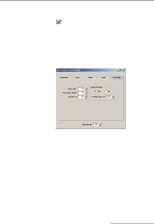
•Collect Effluent – Select the desired action for effluent fluid as it comes off the column. If Yes is selected, enter the desired fraction size.
|
| Note |
| |
|
| The Elute tab is a “Gradient” block type. See Appendix A. |
| |
3.5.5 Flush Settings | This block pumps fluid to flush remaining sample from the | |||
| column and system tubing. This step can prepare the column for | |||
| the next purification run, storage, or disposal. | |||
| The Flush tab is a fluid block type, therefore the settings dis- | |||
| played on this tab are the same as the Equilibrate and Wash | |||
| tabs. Refer to section 3.5.1 for a discussion on the settings for this | |||
| tab. | |||
|
|
|
|
|
|
|
|
|
|
|
|
|
|
|
Figure 3-6 Flush tab settings
3.5.6Saving the Method File To be used in an experiment file, the method file must be saved. Save the method by selecting the File>Save menu command. Use a descriptive file name so that it can be located later.
3.6 Experiments
An experiment file can be created by:
•selecting the File>New>Experiment menu command,
•pressing the Ctrl+E keyboard buttons,
•or by clicking the E toolbar button.
Before building and displaying the experiment file, you must select a method file that will be used for all ten channels. In the Select a Method for Experiment dialog box, locate and highlight the method file, then click the Open button.
An experiment file displays operating parameters in a table. Many of the columns in the table are determined by the template file used to create the method file. (Refer to Appendix A for more details on the template file.) Default values will be assigned to the table cells from the method file you’ve chosen.