Chapter 1: Introduction
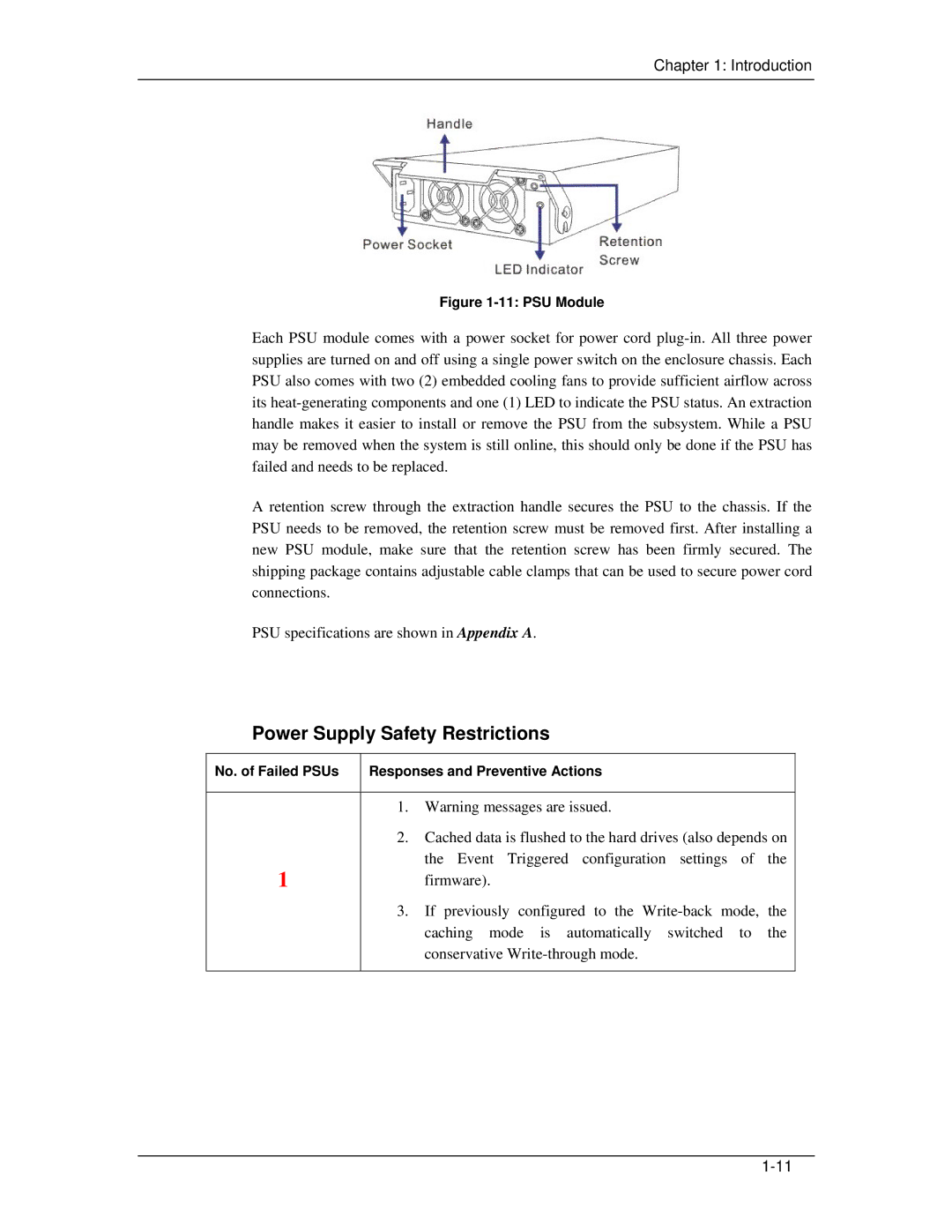
Figure 1-11: PSU Module
Each PSU module comes with a power socket for power cord
A retention screw through the extraction handle secures the PSU to the chassis. If the PSU needs to be removed, the retention screw must be removed first. After installing a new PSU module, make sure that the retention screw has been firmly secured. The shipping package contains adjustable cable clamps that can be used to secure power cord connections.
PSU specifications are shown in Appendix A.
Power Supply Safety Restrictions
No. of Failed PSUs | Responses and Preventive Actions | |
|
|
|
| 1. | Warning messages are issued. |
| 2. | Cached data is flushed to the hard drives (also depends on |
1 |
| the Event Triggered configuration settings of the |
| firmware). | |
| 3. | If previously configured to the |
|
| caching mode is automatically switched to the |
|
| conservative |
|
|
|