Chapter 1: Introduction
the subsystem model name. A different name can be assigned for the subsystem or specific logical drives. This enables ease of identification in a topology consisting of numerous arrays.
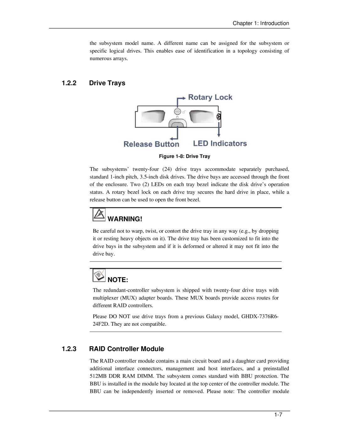
1.2.2Drive Trays
Figure 1-8: Drive Tray
The subsystems’
![]() WARNING!
WARNING!
Be careful not to warp, twist, or contort the drive tray in any way (e.g., by dropping it or resting heavy objects on it). The drive tray has been customized to fit into the drive bays in the subsystem and if it is deformed or altered it may not fit into the drive bay.
![]() NOTE:
NOTE:
The
Please DO NOT use drive trays from a previous Galaxy model,
1.2.3RAID Controller Module
The RAID controller module contains a main circuit board and a daughter card providing additional interface connectors, management and host interfaces, and a preinstalled 512MB DDR RAM DIMM. The subsystem comes standard with BBU protection. The BBU is installed in the module bay located at the top center of the controller module. The BBU can be independently inserted or removed. Please note: The controller module