Galaxy
Each RAID controller module comes with four (4) SFP host ports, two (2)
1.1.1.6 The Backplane Board
An integrated backplane board receives disk drives on the front end and connects the RAID controller, cooling, and PSU modules on the other side. The PCB board provides logic level signals and low voltage power paths. It contains no
1.1.1.7 Subsystem Rack/Cabinet Installation
The subsystem chassis has
The slide rails come with their own printed copies of installation guide.
1.2.Subsystem Components
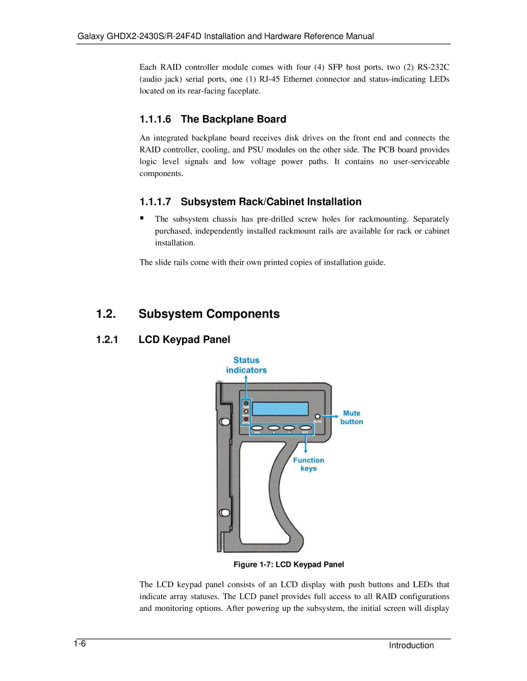
1.2.1LCD Keypad Panel
Figure 1-7: LCD Keypad Panel
The LCD keypad panel consists of an LCD display with push buttons and LEDs that indicate array statuses. The LCD panel provides full access to all RAID configurations and monitoring options. After powering up the subsystem, the initial screen will display
|
|
|
Introduction | ||